
Telephone Line Indicator
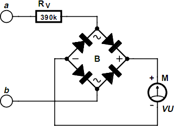
The voltmeter circuit designed for monitoring telephone line status employs a moving coil meter, which is known for its accuracy and simplicity. The inclusion of a bridge rectifier allows for the conversion of alternating current (AC) signals, such as the ringing voltage, into direct current (DC) signals that the moving coil meter can interpret. This enables the meter to respond appropriately to the various voltage levels present on the telephone line.
The series resistor plays a critical role in determining the sensitivity of the meter. By selecting an appropriate resistor value, the circuit can be calibrated to provide meaningful readings across the different states of the telephone line. The optimal resistor values mentioned—390 kΩ for a 250 µA meter and 680 kΩ for a 100 µA meter—ensure that the voltmeter operates within safe limits while providing clear visual feedback on the line's status.
The design must also consider safety measures due to the potentially dangerous voltages involved, particularly during ringing. It is advisable to incorporate protective features such as insulated enclosures or barriers to prevent accidental contact with live components. Additionally, the circuit can be designed to include fuses or circuit breakers that would disconnect the circuit in the event of a fault, further enhancing user safety.
Overall, this voltmeter circuit serves as an effective tool for monitoring telephone line activity, providing clear visual indications while maintaining a high degree of safety and reliability.With the aid of an (old) moving coil instrument it is very little effort to make a simple voltmeter that, at a glance, indicates the status of a telephone line. Because the input impedance of this circuit is very high, there is no problem in having it permanently connected to the line, since it only draws a tiny amount of current.
The schematic sh ows that the circuit consists of no more than a series resistor, a bridge rectifier and a moving coil meter. The value of the resistor depends on the sensitivity of the moving coil meter. In his prototypes, the author used old VU meters that require 250 µA for full-scale deflection. A resistor value of 390 k appeared to be optimal for these meters. For a 100- µA-instrument, this resistor value will have to be increased to about 680 k. The starting point, when selecting a resistor value is that when the telephone is not in use, the meter should de‚ect about 2/3rd of full scale.
The amount of meter deflection indicates the three different states of the telephone line: 1. The deflection is very small: the line is in use (voltage 5 to 12 V). 2. The deflection is 2/3rd of full scale: the line is not in use (voltage typically 48 V). 3. Full-scale deflection: ring signal (60 to 90 V AC). Because the idle voltage and certainly the ring voltage are high enough to be dangerous, it is recommended that the circuit is constructed in such a way that it presents no hazard when touched. 🔗 External reference
Related Circuits
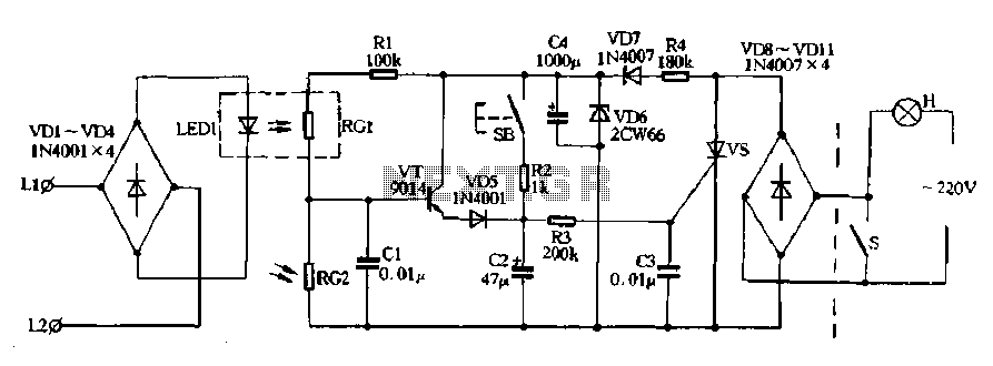
Diodes VD8 to VDI1 function as part of the main circuit isolation, with SCR serving as a composition control switch. The buck regulator circuit is composed of a stable orbital tube VD6 and a simple resistor-capacitor combination (C4). The...
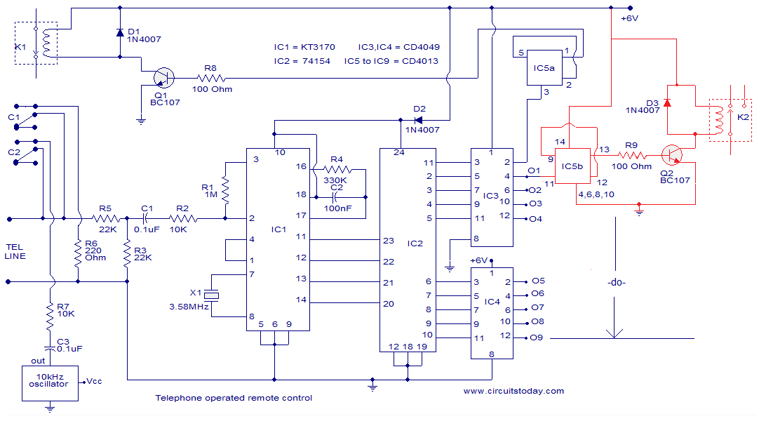
The circuit described is a telephone-operated DTMF remote control that can switch up to nine devices using the telephone keys 0 to 9. The digit 0 is utilized to toggle the telephone system between remote switching mode and normal...
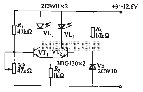
When the battery voltage is within the range of 7 to 12.6V, the light-emitting diode VLi illuminates, maintaining a consistent brightness. If the battery voltage drops below 7V, VLi begins to emit a red light, and the brightness of...

The circuit operates by sending ringing pulses through capacitor C1, resistor R1, and diode D2 to charge capacitor C2 to a voltage of 6V. This voltage causes transistors N1 and N2 to reverse, which activates V1, the analog hook,...
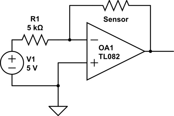
The installation involves a solid-state OEM water depth sensor designed for continuous fluid level measurement. This sensor outputs a resistive signal that is inversely proportional to the liquid level: as the liquid level decreases, the output resistance increases, and...
The circuit is designed for a broadband linear detection application with a bandwidth of 10 MHz. It serves as a millivoltmeter measuring instrument suitable for frequencies exceeding 10 MHz. The circuit features a linear detector utilizing operational amplifiers, specifically...
Warning: include(partials/cookie-banner.php): Failed to open stream: Permission denied in /var/www/html/nextgr/view-circuit.php on line 713
Warning: include(): Failed opening 'partials/cookie-banner.php' for inclusion (include_path='.:/usr/share/php') in /var/www/html/nextgr/view-circuit.php on line 713