
Telephone operated remote
The telephone-operated DTMF remote control circuit is designed for efficient and reliable operation in switching multiple devices remotely. At its core, the circuit employs the KT3170 DTMF decoder, which is pivotal for translating the DTMF tones received from the telephone into a format suitable for control logic. The BCD output from the KT3170 is fed into the 74154 demultiplexer, which effectively routes the decoded signals to the appropriate output lines corresponding to the keys pressed on the telephone.
The dual D flip-flop IC CD4023 serves as a state controller, allowing for toggling of device states based on the DTMF input. The use of flip-flops ensures that the system can maintain the state of each device even after the control signal is removed, providing a stable operation. The relays used in the circuit are critical components that physically switch the devices on and off. Relay K1, controlled by transistor Q1, is responsible for establishing the connection to the telephone line and enabling the remote mode.
The audio feedback provided by the 10 kHz signal is an important feature, ensuring the user is aware of the system's operational status. This feedback mechanism is essential for user experience, confirming that the system is ready for further commands.
Additionally, the circuit's design incorporates safety features such as the 220 Ohm loop, which prevents unwanted ringing and ensures that the telephone line remains clear for communication. The choice of CMOS technology for the various ICs used in the circuit contributes to low power consumption, making the system suitable for prolonged use without the need for frequent battery replacements or power interruptions.
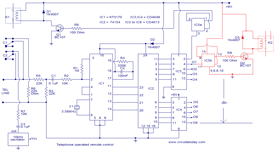
Overall, this telephone-operated DTMF remote control circuit exemplifies a practical application of digital electronics in remote device management, showcasing the integration of various components to achieve a seamless and user-friendly experience.The circuit given below is of a telephone operated DTMF remote. The circuit can be used to switch up to 9 devices using the keys 0 to 9 of the telephone. Digit 0 is used to switch the telephone system between remote switching mode and normal conversation mode. IC KT3170 (DTMF to BCD decoder) is used to decode the DTMF signals transmitted over the telephone line to corresponding BCD format. IC 74154 ( 4 to 16 demultiplexer) and IC CD4023 (dual D flip flop) is used to switch the device according to the receive DTMF signal. The operation of the circuit is as follows. After hearing the ringtone from the phone at receiver end, press the 0 button of the remote phone. The IC1 will decode this as 1010. The pin 11 of IC2 will go low and after inversion by the NOT gate in IC3 it will be high. This will toggle the flip flop IC5a and the transistor Q1 will be switched on. This will make the relay K1 ON. The two contacts C1 and C2 of the relay K1 will be closed. C1 will form a 220 Ohm loop across the telephone line in order to disconnect the ringer from the telephone line (this condition is similar to taking the telephone receiver off hook).
C2 will connect a 10KHz audio source to the telephone line in order to inform you that the system is now in the remote switch mode. Now if you press 1 on the transmitter phone, the IC1 will decode it as 0001 and the pin 2 of IC2 will go low.
After inversion by the corresponding NOT gate inside IC3, it will be high. This will toggle flip flop IC5b and transistor Q2 will be switched ON. The relay will be energized and the device connected through its contacts gets switched. Pressing the 1 again will toggle the state of device. In the same ways Keys 2 to 9 on the transmitter phone can be used to toggle the state of the device connected to the channels O2 to O9. After switching is over, press the O key on the transmitter phone in order to toggle the flip flop IC5a to de-energize the relay K1.
The 200 Ohm loop will be disconnected from the line, the 10 KHz audio source will be removed and the telephone receiver will be ready to receive new calls. The IC KT 3170 used here is a low power DTMF receiver IC from Samsung. The IC is fabricated using low power CMOS technology and can detect all the 16 standard DTMF tones. The DTMF signal received will be decoded to a BCD output for switching applications. 74154 is a 4 line to 16 line decoder from national semiconductors. It decodes a 4 bit input code into one of 16 mutually exclusive outputs. Maximum supply voltage is 7V and normal power dissipation is around 175mW. CD4049 is a CMOS hex inverter from Texas Instruments. Each of the IC contains six NOT gates. Maximum supply voltage possible is 20V and each gate can drive up to two TTL loads. CD4013 is a CMOS dual D filp flop. Each flip flop has independent data, reset Q, Qbar, clock and set pins. The maximum possible supply voltage is 15V and the IC has high noise immunity. 🔗 External reference
Related Circuits
Digital Remote Thermometer. The remote sensor transmits data through the mains supply. The temperature range is from 0.0 to 99.9 °C. Transmitter circuit diagram includes the following components: R1, R3 = 100K 1/4W resistors; R2 = 47Ω 1/4W resistor;...
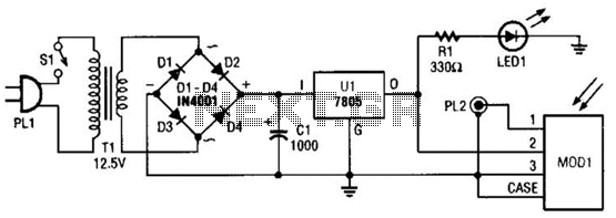
A schematic diagram for the remote analyzer is presented. The circuit is powered by a simple 5-V supply, which includes components such as PL1, SI, Tl, a bridge rectifier formed by diodes D1 through D4, capacitor CI, and a...
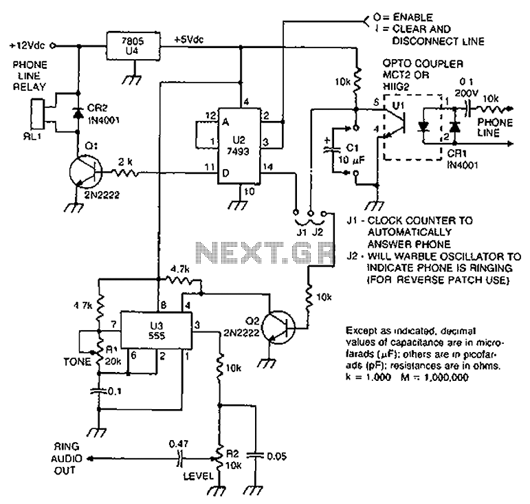
Check the loop circuit for an automatic telephone answering system or a tone generator for use in reverse automatic repair. The loop circuit in an automatic telephone answering system is designed to detect incoming calls and activate the answering mechanism....
An infrared wired repeater circuit is designed to control appliances from a remote location. Parts List: R1: 1k Resistor (1), R2: 3.3k Resistor (1), R3: 10k Resistor (1). The infrared wired repeater circuit serves as an interface for controlling various...

This circuit utilizes a simple calculator along with a chip-on-board (COB) from an analog quartz clock to create a telephone call meter. The calculator converts STD/ISD calls into local call equivalents and continuously displays the current local call meter...
The IR Tester circuit indicates whether the button pressed on a remote control is functioning. Q1 is a phototransistor that is activated by infrared (IR) energy. The IR Tester circuit operates by detecting infrared signals emitted by remote control devices...
Warning: include(partials/cookie-banner.php): Failed to open stream: Permission denied in /var/www/html/nextgr/view-circuit.php on line 713
Warning: include(): Failed opening 'partials/cookie-banner.php' for inclusion (include_path='.:/usr/share/php') in /var/www/html/nextgr/view-circuit.php on line 713