
Zener Tester schematic

More: With the resistors in the circuit selected is the current approximately 1mA, 2mA, 5mA, 10mA and 20mA. Great precision is not necessary. If meter is chosen here a little DVM module. But every other meter can be used if the input resistance but high enough. Construction: The circuit is simple to build on a piece of PCB holes. Note that the DVM module of the circuit a separate isolated power supply needs. Instructions: Connect the test zener diode between the A and K connector. Start with a current of 2mA. This is a safe value for most types of zener diodes. Depending on the type of zener diode, a larger current can be selected. The Zener voltage will vary slightly. Join the zener diode on backwards, the meter will indicate approximately 0.7 V. The same image shows a normal silicon diode. A germanium diode, a voltage of about 0.3 V to 0.4 V, while indicating a Schottky about 0.2 V indicates. Join an LED on A and K, it will light and the V forward (the LED voltage) of the LED indicate. The diode / LED indicates the faulty meter is zero if the voltage on the collector of Q1 is, this is> 25V. Rectifier bridge BR1 = 40V 500mA R1 = 3K3 ¼ W R2 = 5K6 ¼ W R3 = 2k7 ¼ W R4 = 1k ¼ W R5 = 560 ohm ½ W R6 = 270 ohm ½ W C1 = 470?F 35V D1 = 6V2 400mW zener Q1 = BC161-16 S1 = on / off switch S2 = 5 position switch contact a parent ENG = The test diode (Device Under Test) DVM DVM = module Bacon and Dick Best (adjusted to 200V input)
This measuring device is designed to evaluate various types of diodes, including Zener, silicon, germanium, Schottky diodes, and LEDs. The circuit operates by utilizing a transistor (Q1, BC161-16) as a switch, powered by a Zener diode (D1, 6V2) that provides a stable reference voltage to the base of the transistor. The emitter resistor (R2, 5.6kΩ) is selected to allow a current of approximately 1mA to flow through the transistor, ensuring that the circuit operates within safe limits for the tested diodes.
The current through the circuit can be adjusted with the resistors, allowing for various test currents (1mA, 2mA, 5mA, 10mA, and 20mA). The DVM module is used to measure the voltage across the diode under test, with the input resistance of the meter being an essential factor to ensure accurate readings.
The construction involves placing the components on a PCB, ensuring that the DVM module is powered separately to avoid interference. The Zener diode is connected between designated points (A and K), and the measuring process begins with a safe current of 2mA. Depending on the diode type, the voltage readings will differ: for example, a backward-connected Zener diode will show approximately 0.7V, while silicon, germanium, and Schottky diodes will display lower forward voltages.
The circuit also includes a rectifier bridge (BR1, rated for 40V and 500mA) and various resistors (R1, R3, R4, R5, and R6) to ensure proper operation and current limiting. The capacitor (C1, 470µF, 35V) is included to stabilize the power supply. The device's functionality allows for quick testing and identification of faulty diodes, with visual feedback provided by the DVM readings.With this simple measuring device can: Determine the Zener voltage up to 25V. The connections of cathode and anode of each diode finding. Check if a diode fails. Silicon, germanium and Schottky diodes distinguish. LED test and the V forward measure Q1 is connected as power supply. Because D1 is a constant tension on the base and there is resistance in the chosen emitteraansluiting approximately 5.6 V. With an R2 emitter of 5K6 will run through the transistor than 1mA. With the resistors in the circuit selected is the current approximately 1mA, 2mA, 5mA, 10mA and 20mA. Great precision is not necessary. If meter is chosen here a little DVM module. But every other meter can be used if the input resistance but high enough. Construction: The circuit is simple to build on a piece of PCB holes. Note that the DVM module of the circuit a separate isolated power supply needs. Instructions: Connect the test zener diode between the A and K connector. Start with a current of 2mA. This is a safe value for most types of zener diodes. Depending on the type of zener diode, a larger current can be selected. The Zener voltage will vary slightly. Join the zener diode on backwards, the meter will indicate approximately 0.7 V. The same image shows a normal silicon diode. A germanium diode, a voltage of about 0.3 V to 0.4 V, while indicating a Schottky about 0.2 V indicates.
Join an LED on A and K, it will light and the V forward (the LED voltage) of the LED indicate. The diode / LED indicates the faulty meter is zero if the voltage on the collector of Q1 is, this is> 25V. Rectifier bridge BR1 = 40V 500mA R1 = 3K3 ¼ W R2 = 5K6 ¼ W R3 = 2k7 ¼ W R4 = 1k ¼ W R5 = 560 ohm ½ W R6 = 270 ohm ½ W C1 = 470?F 35V D1 = 6V2 400mW zener Q1 = BC161-16 S1 = on / off switch S2 = 5 position switch contact a parent ENG = The test diode (Device Under Test) DVM DVM = module Bacon and Dick Best (adjusted to 200V input)
🔗 External reference
Related Circuits
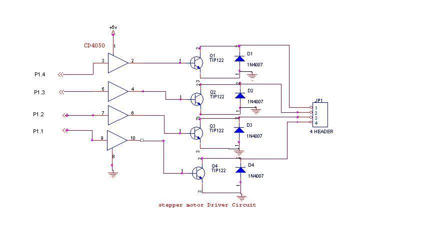
A 6V, 2A stepper motor is utilized in this circuit. The CD4050 hex buffer is employed to connect to the microcontroller. The output of the CD4050 is linked to the base of a TIP122 transistor. The emitter and collector...
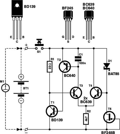
Determining whether a battery is empty or if there is a fault with a device can be challenging when a battery-powered device, such as a Walkman, fails to power on. Before seeking professional repair, it is advisable to test...
This circuit will detect AC line currents of about 250 mA or more without making any electrical connections to the line. Current is detected by passing one of the AC lines through an inductive pickup (L1) made with a...
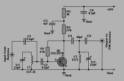
This is a simple circuit of an FM booster designed to enhance the reception of programs from distant FM stations. The amplifier effectively captures signals from far-off FM stations. The configuration is set up as a common-emitter tuned RF...
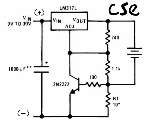
This is a straightforward charger designed for 9V to 30V batteries, primarily operated by the IC LM317L and a 2N222 transistor. It utilizes direct input DC voltage, and a recommended capacitor of 1000µF is included for filtering the output...
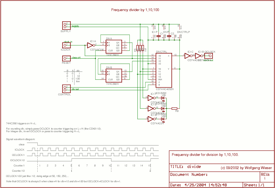
The divider design is straightforward. Users can select a division factor of 1, 10, or 100, or opt for no output (tied low) through the CONTROL input connected to the analog multiplexer HC4052. The design utilizes AC04 to drive...