
Telephone off-hook indicator

No description available.
Related Circuits
This circuit is designed to indicate the power output level of any audio amplifier. It is simple, portable, and displays three power levels that can be set to any desired value. The circuit operates by utilizing a combination of resistive...
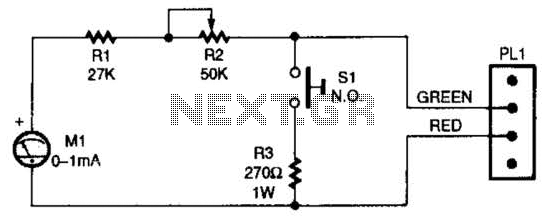
When the switch SI is pressed, the silicon-controlled rectifier (SCR) is activated, connecting LED1 and resistor R1 across the telephone line. This action causes the line voltage to drop to approximately 20 volts, which maintains the connection to the...
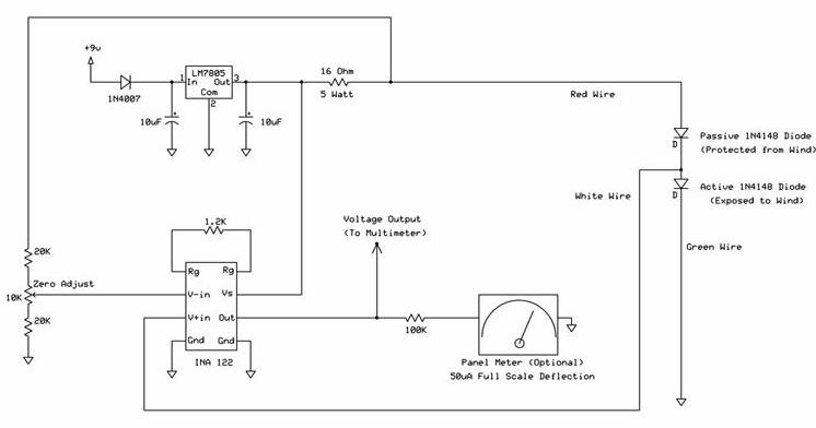
The following circuit illustrates a wind speed indicator circuit. It operates with a constant 5 VDC output provided by the LM7805 voltage regulator, using a 9 VDC supply. The wind speed indicator circuit is designed to measure and display wind...
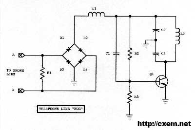
Wireless Telephone Bug. This project enables monitoring of a phone line as soon as the phone is off-hook. A regular FM broadcast band radio can be utilized for this purpose. The Wireless Telephone Bug is a circuit designed to allow...
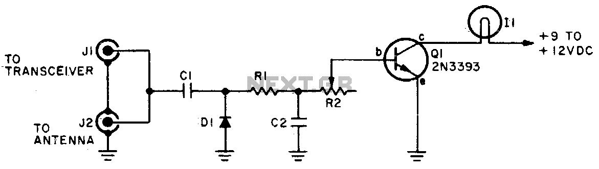
The brightness of the indicator lamp changes in accordance with the modulated RF signal. Adjust resistor R2 while the transmitter is on (modulated) until the lamp flashes in sync with the modulation. Cl = 5 pF, C2 = 100 pF,...

An intercom utilizing dual-modular wall jacks is depicted in this circuit. If the wires are accessible in the home telephone cable, this system can be installed with minimal difficulty. The intercom system described employs dual-modular wall jacks, which are standard...