
Water Level Indicator With 7-Segment Display PCB
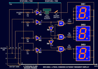
This water level indication circuit employs a 7-segment LED display for clear numeric representation, enhancing visibility compared to traditional LED indicators. The inclusion of a buzzer provides an auditory alert for overflow conditions, ensuring that users are promptly notified to prevent potential water spillage. The circuit operates based on the principles of digital logic using the 7404 NOT gate IC, which is configured to respond to varying input voltages corresponding to the water level.
The 1M ohm resistor serves a dual purpose: it pulls the gate input high under normal conditions and establishes a reference voltage level for the operation of the circuit. As water fills the tank, the conductive properties of the water engage the low-level sensor, which is strategically placed to trigger the necessary logic changes in the circuit. The cascading logic levels from the NOT gates effectively convert the analog water level into a digital signal that can be interpreted by the display.
The display outputs "L" when the water level is low, transitioning to "H" for half-full and "F" for full, allowing for easy monitoring of the tank's status. This design can be integrated into automated water tank systems where it can control the motor operation based on the water level readings, thereby enhancing efficiency and convenience. The circuit's modular design allows for adaptability in various applications, making it suitable for both residential and industrial water management systems.Circuits available for indicating water level is usually consist of LEDs to indicate the liquid level. But this circuit uses a 7-segment LED display instead of normal LED`s for numeric display of water level.
Moreover, a buzzer is used to alert you of water overflowing from the tank. The circuit shows the water level by displaying L, H and F for lo w, half and full, respectively. You can use this circuit for water tank motor control or a stand alone circuit. pins of IC 7404 (NOT gate IC) are pulled high via a 1M ohm resistor. So it outputs a low voltage. As water starts filling the tank, a low voltage is available at the input pins of the gate and it outputs a high voltage. When the water in the tank rises to touch the low level sensor, pin 5 of gate N3 gets a low voltage and results in high output at pin 6.
Pin 6 of the gate is connected to pin 10 of gate N9, so pin 10 also goes high. Now as both pins 9 and 10 of gate N9 are high, its output pin 8 also goes high. As a result, positive supply is applied to DIS3 and it shows L` indicating low level of water in the tank. 🔗 External reference
Related Circuits
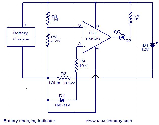
This simple circuit can be used to monitor whether a battery is charging. The voltage comparator IC LM393 is the core component of this circuit. The LED D1 will remain ON whenever there is at least 25 milliampere current...
Nearly all modern computers are equipped with logic blocks that facilitate the implementation of a USB port. A USB port can deliver over 100 mA of continuous current at 5V to peripherals connected to the bus. Therefore, it serves...
The area has been experiencing a drought for over a year, resulting in water restrictions on activities such as washing cars and watering gardens. In regions affected by prolonged drought, water conservation becomes critical. Water restrictions are typically implemented to...
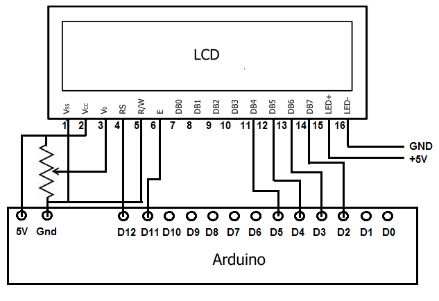
To achieve this, the first step involves establishing the necessary physical connections between the Arduino board and the LCD. Following this, code must be written to display the desired text on the LCD. LCDs have become the standard means...
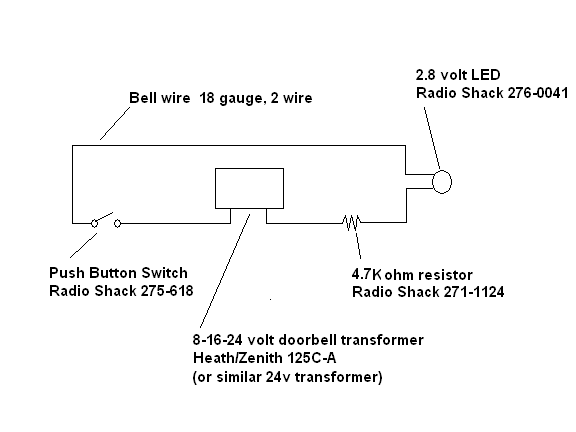
There are battery-powered wireless systems available, but the ones encountered would indicate that the door was open even if it was left ajar for ventilation. A system was desired that would alert when the door was fully raised. Additionally,...

This design explains how to use an encoder to set the number shown by a 7-segment display. Turn the knob clockwise to increment the number, turn it counterclockwise to set it back. Encoders are the most practical way to...