
Oscillators for Buzzers and telephone Earpieces
The first circuit utilizes a magnetic telephone earpiece, which serves as the sound-producing element. The circuit configuration requires a transistor, typically a bipolar junction transistor (BJT), and a capacitor. The transistor operates as a switch, allowing current to flow through the earpiece, generating sound waves. The frequency of the output sound is determined by the capacitor value; thus, changing the capacitor will yield different frequencies. The recommended operating frequency for this circuit is approximately 1800 Hz, suitable for generating a clear tone.
In the second circuit, a ceramic sounder is employed, which inherently has a capacitive property that allows it to generate sound without the need for an additional capacitor. This circuit operates at a frequency of around 800 Hz, making it ideal for low-power applications. The power requirements for this circuit are notably low, with an operating voltage range of 9.5 to 20V.
Both circuits are designed for low sound output levels, making them appropriate for applications where minimal sound is acceptable, such as in portable devices or low-power audio signaling systems. The current drain is also minimal, contributing to the efficiency of these designs. It is important to note that not all transistors will function effectively in these circuits; therefore, specific transistor types should be used. The BC109 and 2N2222A transistors are recommended, as they have been tested for compatibility with the described circuits, although they may operate at slightly different voltage levels compared to other specified transistors. These simple buzzer circuits exemplify an effective use of minimal components to achieve audio signaling functionality.In order to generate a single note you may try these simple circuits. With only three components you may implement some basic buzzers. You need a telephone earpiece for the first circuit. Any old telephone set has got one of those magnetic earpiece that is right for our purposes. Add an extra capacitor and a transistor and you have your buzzer. Frequency of operation is about 1800 Hz and the capacitor must be changed if you wish to have a different frequency. The second circuit is implemented with a ceramic sounder: its intrinsic capacity is used to make another simple buzzer.
Working frequency is 800 Hz and power drain is really low. The operating voltage is 9,5 - 20V for the circuit with the ceramic sounder and 8 - 16V for the other circuit. Do not expect a loud sound level: it is rather limited just as the current drain is. These buzzers are suitable for audio signaling on portable devices and wherever it is necessary to have a sound source implemented with a minimum components count.
Not all transistors will oscillate: you have to use the specified type although I found that the BC109 and 2N2222A will also work albeit at a slightly different voltage. 🔗 External reference
Related Circuits
Today, phones have become an integral part of daily life and are the most widely used communication tool globally. Due to their immense popularity and widespread use, there is a growing need for call recording devices, which are utilized...
The circuit serves as a foundational design, requiring experimentation for specific applications. In popular microwave bands, local oscillators (LOs) are typically generated using overtone crystal oscillators followed by multipliers. A table presents the standard LO frequencies for narrowband segments,...
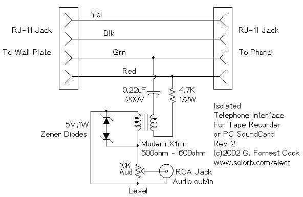
There's not much to this circuit. The two RJ-11 jacks are set up to feed the telephone circuit through from the wall to the phone. The active signal for a single phone is on the red and green wires....
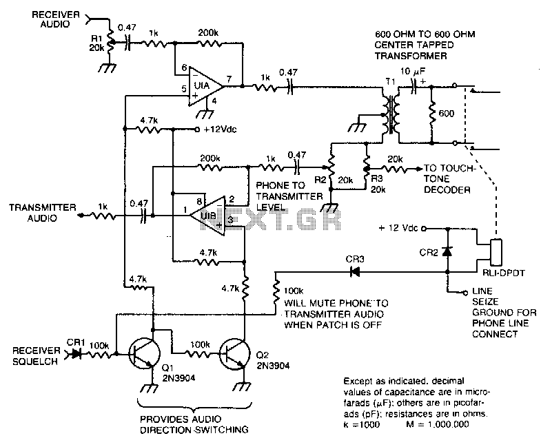
This circuit facilitates the communication link between the receiver and the phone line, as well as the phone line and the transmitter, utilizing an operational amplifier (op-amp) for signal amplification. The described circuit connects a receiver to a phone line...
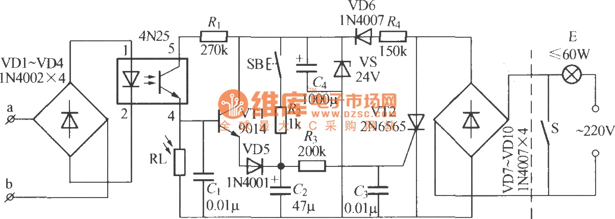
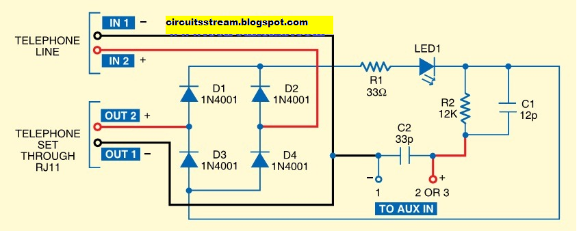
The diagram illustrates an automatic lighting control circuit activated by a telephone. At night, when the telephone rings or the user picks up the receiver, the light turns on. If the telephone stops ringing (when no one is listening)...
While conversing with a distant subscriber on the telephone, it is common to experience frustration due to faint audio that is barely intelligible. To address this issue, an inexpensive amplifier circuit is proposed. This circuit can be easily assembled...