
Lantern making use of a relay control circuit
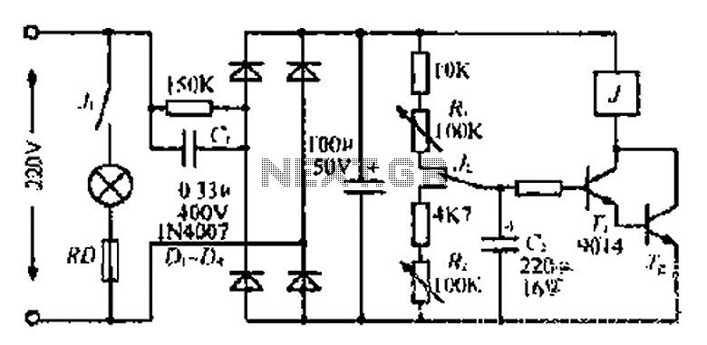
This circuit serves as a power supply and control mechanism for low-voltage lighting systems. The use of a 220V AC mains supply is standard in many regions, and the initial stage of the circuit involves a capacitive dropper to reduce the voltage for safe processing. The 0.33 µF capacitor (Ci) acts as a filtering component, allowing only the AC component to pass through while dropping the voltage to a manageable level.
The bridge rectifier, consisting of four diodes (D1 to D4), converts the incoming AC voltage to DC. This rectification is crucial for powering devices that require a stable DC supply. Following this, the 100 µF capacitor acts as a smoothing capacitor, reducing ripple in the DC output and providing a more stable voltage to the subsequent components.
The control circuit operates at a threshold voltage, which is monitored to ensure proper operation. When the voltage exceeds a certain limit, the circuit engages the lighting system. The 10 kΩ resistor (Ri) plays a role in charging the capacitor (C2), which is essential for the timing and control functions of the system. The operation of the lights is governed by a relay (L2) that is controlled by the state of the contacts, which change based on the voltage levels.
The inclusion of a photoelectric sensor (C1) allows the system to respond to ambient light conditions, potentially enabling automatic on/off functionality based on surrounding light levels. This feature enhances the efficiency of the lighting system, ensuring that lights are only activated when needed.
Overall, this circuit is designed to provide a reliable and efficient means of controlling low-voltage lighting using standard mains electricity, incorporating features such as voltage regulation, timing, and light sensing to optimize performance.220V mains electricity sent through 0.33 u F (Ci). ] 50kn ohmic drop Sui, Di - D4 bridge circuit composed of rectifier. After 100 u F capacitor filter technology,: [born about 2V (iiIU source control circuit skewer beginning Ding ashamed towels, electricity on rG. When the pressure began to ov, save n, Tz off, no suction units, not bright lights In this case the power supply by iOk n electrical resistance, Ri, often just contact charging C2 .Q dagger electronic music rises to a certain extent, the mantle Taiwan, point lights are bright. At this time, normally closed contact off open, normally open contact conduction .c through 4.7k fl resistor, R, discharge and after a predetermined time after .J release L2, lights off .c1 photoelectric again, after a period of time after tI.
a., i died station, colored lights, pocket. such a process may go bite cycle F,
Related Circuits
The curves for a capacitor exhibit significant non-linearity, which can be utilized in circuits to modulate, demodulate, and multiply frequencies. This characteristic is known as non-linear reactance rather than resistance, resulting in minimal energy loss. The charge stored in...
A DC power supply with a shunt, rectifier, filter, current limiting, and voltage regulation, providing 10V voltage outputs. The circuit is simple and low cost, designed to meet the requirements of various applications. Additionally, it features a 3V indicator...
This analog switch utilizes the 2N4860 JFET, which features a low on-resistance (rON) of 25 ohms and minimal leakage current. The LM102 acts as a voltage buffer in the circuit. It is designed to be adaptable for use in...
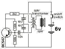
The Colpitts Oscillator is characterized by tapping the mid-point of the capacitive side of the oscillator section. The inductor can be the primary side of a speaker transformer. The feedback comes via the inductor. The Colpitts Oscillator is a type...
MSP430 microcontroller and I2C-compatible slave peripheral device. Temperature measurement tasks can be accomplished in a variety of ways. The MSP430 microcontroller is a low-power, 16-bit device widely used in embedded systems, particularly for applications requiring efficient power management and precise...
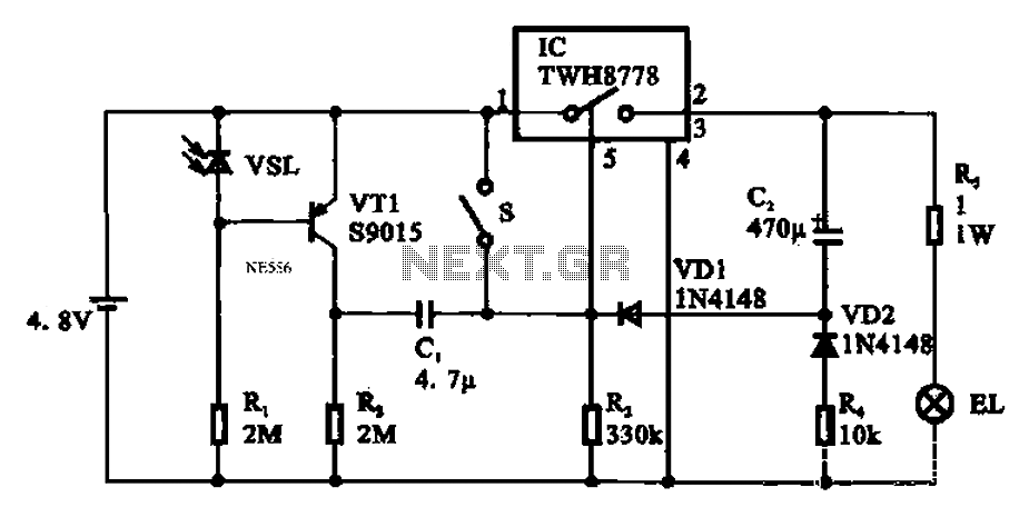
Automatic emergency lamp circuit featuring an electronic switch integrated circuit. This circuit is designed for automatic emergency lighting. The system operates based on ambient light conditions; when light levels are low at night, the circuit activates the emergency lamp....