
Telephone ring amplifier
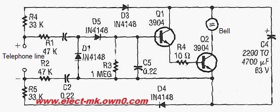
The telephone ring amplifier circuit serves to enhance the ringing signal of a telephone, making it audible through a service speakerphone. This circuit is particularly useful in environments where the standard ringing sound is insufficient due to background noise or distance from the telephone.
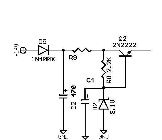
The primary components of the circuit include two resistors, a 33 kΩ resistor and a 47 kΩ resistor, which are used to set the gain of the amplifier and control the ringing signal's amplitude. The resistors are connected in a configuration that allows for proper signal conditioning.
In addition to the resistors, the circuit may include an operational amplifier (op-amp) configured in a non-inverting mode to amplify the incoming ringing signal from the telephone line. The op-amp increases the voltage level of the ringing signal, making it more audible through the speakerphone.
Capacitors may also be included to filter out any noise and ensure that only the ringing frequency passes through to the amplifier stage. The output of the op-amp can be connected to a speaker or a piezo buzzer, which converts the amplified electrical signal back into sound.
Power supply considerations are also crucial; the circuit typically requires a DC voltage source, which can be derived from the telephone line or an external adapter. Proper decoupling capacitors should be placed near the power supply pins of the op-amp to stabilize the voltage and prevent oscillations.
This telephone ring amplifier circuit is a practical solution for enhancing the ringing sound in various applications, ensuring that the ringing signal is loud enough to be heard clearly in noisy environments.Telephone ring amplifier of Service Speaker phone ringing bell Circuit diagram Electronic items Resistance of 33 kilo ohms 2 Resistance 47 Kilo Ohm. 🔗 External reference
Related Circuits
To design a Tube Headphone Amplifier we need a triode with uncommon characteristics: enough voltage gain, low internal resistance and good anodic current. My first test was done with the E182CC, but there is the limitation on the usable...
This low-cost project enables audio reproduction from a television without disturbing others. It eliminates the need for wired connections between the TV and loudspeakers. Instead, it utilizes invisible infrared light to transmit audio signals from the TV to the...
This Class E RF amplifier is capable of delivering up to 400 watts of RF output, depending on the input voltage and tuning parameters (current). The amplifier employs economical IXDD414 Driver ICs, with one driver for every two MOSFETs....
Building a solid-state linear amplifier. An old Heathkit SB 221 has undergone a major overhaul and redesign, and is now functioning well on 80, 40, 20, and 15 meters; however, it does not operate on 17, 12, and 10...
The D-200W module features a unique design that includes overload, overvoltage, overheating, short circuit, and reverse polarity protection, as well as shock protection for various speakers. The module employs a synchronous dynamic bias circuit to minimize static power consumption,...
In order to generate a single note you may try these simple circuits. With only three components you may implement some basic buzzers. You need a telephone earpiece for the first circuit. Any old telephone set has got one...
Warning: include(partials/cookie-banner.php): Failed to open stream: Permission denied in /var/www/html/nextgr/view-circuit.php on line 713
Warning: include(): Failed opening 'partials/cookie-banner.php' for inclusion (include_path='.:/usr/share/php') in /var/www/html/nextgr/view-circuit.php on line 713