
Telephone Silencer
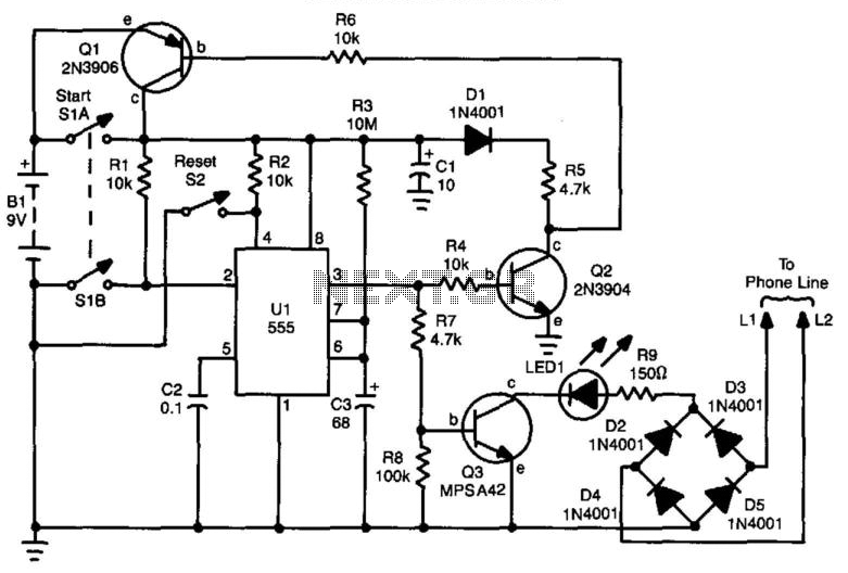
This circuit design utilizes an astable multivibrator configuration, implemented with operational amplifier U1, to generate a continuous square wave output. The timing components, resistor R3 and capacitor C3, define the duration for which the busy signal is to be maintained. The values of R3 and C3 can be calculated using the standard astable multivibrator formula, allowing for precise control over the timing interval, which can be set to a maximum of 10 minutes.
The operation begins when switch SI A is engaged, initiating the oscillation of U1. This action also triggers transistor Q1, which acts as a latch to keep the circuit powered during the timing interval. The latching mechanism ensures that the busy signal is maintained even if SI A is released before the timing cycle is complete.
As the timing interval approaches completion, the output from U1 will eventually deactivate, leading to the cutoff of power through transistors Q2 and Q3. This design allows for a seamless transition back to the normal state of the phone line, ensuring that the user can resume regular phone operations without manual intervention.
Additionally, switch S3 plays a critical role in simulating the off-hook condition by placing a 150-ohm resistor across the phone line. This mimics the electrical characteristics of a phone that is off the hook, thereby generating a busy signal for incoming callers. The use of a resistor rather than a relay or more complex switching mechanism contributes to the simplicity and reliability of the circuit.
Overall, this busy signal generator circuit is an effective solution for users who need to manage incoming calls without direct interaction, providing both convenience and functionality. If you are busy and cannot answer or do not wish to answer your phone, this circuit will give a busy signal without you having to leave the phone off the hook. After a predetermined time, the circuit is deactivated. U1 forms an astable multivibrator that can be set for a time up to 10 minutes by values of R3 and C3. When SI A is depressed, U1 starts, and Ql latches, which powers the circuit. At the end of a time interval determined by R3 and C3, Q2 and Q3 cut off and remove power from the circuit.
During the operation, S3 throws a 150- resistor across the phone line, which simulates an off-hook condition. 🔗 External reference
Related Circuits
In the past, when telephones were relatively simple devices, there were minimal electrical issues to address. Telecom operators implemented surge protection for all telephone lines that were at risk from storms. Ironically, as technology has advanced and more delicate...
This circuit generates a ringing sound similar to that produced by modern telephones. It comprises three nearly identical oscillators connected in a series configuration, each generating a square wave signal. The frequency of each oscillator is determined by the...
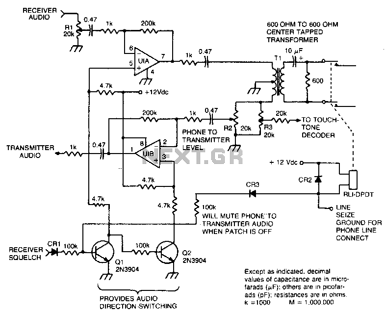
This circuit facilitates the communication link between the receiver and the phone line, as well as the phone line and the transmitter, utilizing an operational amplifier (op-amp) for signal amplification. The described circuit connects a receiver to a phone line...
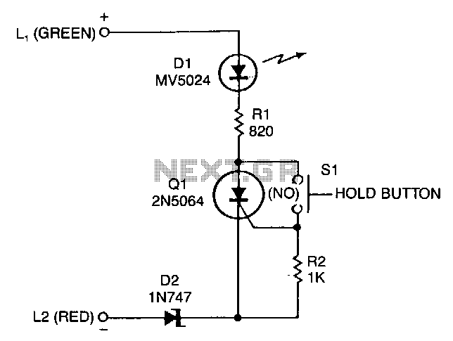
A sensitive-gate SCR provides a line-holding current of 20 to 40 mA, depending on loop resistance. It also lights an LED to give the user a positive indication that the telephone line is on hold. The 20 to 40...
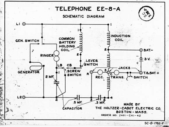
One unit is housed in a leather bag and is identified as model EE-8-A. One or more units are contained in a canvas bag and are designated as EE-8-B. All models feature handsets equipped with a butterfly push-to-talk lever....
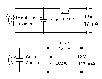
In order to generate a single note you may try these simple circuits. With only three components you may implement some basic buzzers. You need a telephone earpiece for the first circuit. Any old telephone set has got one...