
EGR 450 Manufacturing Controls Project
The timing and counting circuit is designed to provide accurate lap timing and counting for a slot car racetrack. The use of integrated circuits, specifically the 74LS90 for counting and the 74LS47 for driving the seven-segment displays, ensures reliability and precision in lap time measurement. The 555 timer generates a stable oscillation that serves as the timing reference, allowing for fine-tuning of the lap timing accuracy. The incorporation of debouncing techniques for the switches is critical to prevent erroneous counts due to mechanical bounce, which is a common issue in switch-based designs.
The circuit's architecture allows for easy scalability; additional circuits can be added to extend functionality or increase display capabilities. The design also considers user interaction, with accessible switches for resetting and powering the system, enhancing usability during operation. The power supply choice is suitable for TTL logic levels, ensuring stable operation without risking damage to the integrated circuits.
Overall, this circuit design exemplifies a practical application of digital logic in a recreational setting, showcasing how integrated circuits can be effectively utilized to create an engaging and functional electronic system for timing and counting in slot car racing.A timing and counting circuit using integrated circuit chips with seven-segment LED displays is used to display current lap time, the previous lap time, and also the total number of laps completed on an assembled 1/64th-scale slot car racetrack. A switch contacted by the car will increment the lap counter, reset the lap timer, and also update the
prior lap ’s time. Two other switches will also be used, one to turn the power on and off, and another to reset the total number of laps completed. This circuit was built using the BCD 0-99 Counter in the Engineer ’s Mini-Notebook on Digital Logic Circuits by Forrest Mims III, available from Radio Shack.
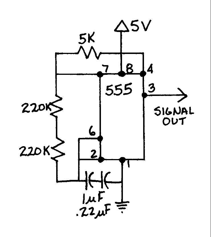
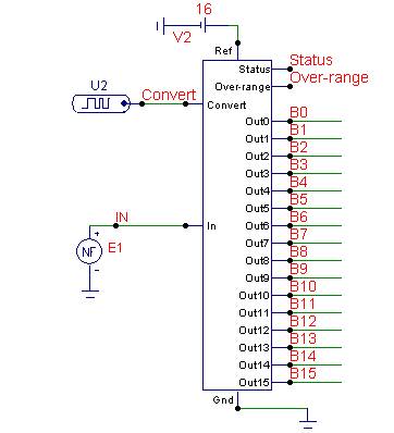
This circuit serves as the output driver for the LED ’s used to display the timer and counter circuit outputs. The schematic for this circuit is shown below as Figure 1. A 555 IC Timer was used to create the oscillating pulse for the input to the display circuit shown in Figure 1.
The output pulse from pin 3 of the timer is wired to pin 14 of the 74LS90 chip in the counter. This circuit was also connected to two more identical circuits showing three digits. This circuit will be used to measure the time to complete a lap on the track ranging from 0. 1 seconds to 99. 9 seconds. The schematic for the timer circuit is shown below as Figure 3. Using the timer above with the shown values, the timing circuit oscillates at 0. 1 Hz giving us a timing display accurate to 0. 1 seconds. For a slower timer, the capacitance needs to be increased. To speed up the timer, the capacitance values need to be lowered. However, a faster timer will be harder to calibrate for accuracy. A flip-flop circuit was used to display the just completed lap ’s time. A 74175 IC inserted between the 74LS90 and 74LS47 IC ’s causes the display to only show the completed time. When the switch is activated by the car, it sends a signal to the display and updates the time. This takes a moment, so inverters are inserted between the switch and the timer display to allow the completed lap ’s time to update before the current lap time is reset.
Without the inverters, the completed lap ’s time sets to zero because the current lap time is reset to zero before the time is updated. The flip-flop schematic is shown below in Figure 4. Note: Only the changes made to the display driver circuit are shown, all other connections remain the same.
This circuit was built from the 0-99 Second/Minute Timer in the Engineer ’s Mini-Notebook on Digital Logic Circuits by Forrest Mims III available from Radio Shack. The input pulse for this circuit will be delivered by a switch that is built into the track. The pin that holds the car to the track will activate the switch causing the timer to increment. This circuit will be used to determine the number of laps that a car completes. The schematic for the circuit is shown below in Figure 5. The switch was debounced to prevent multiple pulses through the switch. The switch is activated on the initial contact and holds that contact momentarily to avoid any extra pulses.
If the switch is activated multiple times, it will increment the timer inaccurately, and will also cause the previous lap time to reset to zero. Since this project was constructed entirely with TTL Integrated Circuits, a maximum input voltage to the circuits was 5 volts.
To supply power to the circuits, an AC to DC converter was purchased at Radio Shack. The converter purchased was the Multi-Voltage 800mA Power Adapter, model number 273-1667. This Multi-Voltage adapter was capable of supplying DC voltages of 3, 4. 5 6, 7. 5 9 and 12VDC and up to 800mA current. Although this power supply has a range of available voltages, any comparable power supply producing 4. 5 VDC – 6 VDC should be suitable. Once all of the individual circuits were designed and tested by themselves, they were all connected together to create the complete system.
The system consists of three separate parts, 🔗 External reference
Related Circuits
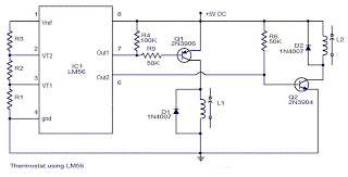
The values of the LM56 thermostat project circuit diagram for resistors R1, R2, and R3 at the travel points VT1 and VT2 can be determined using the following equations. This electronic circuit thermostat with the IC LM56 serves as...
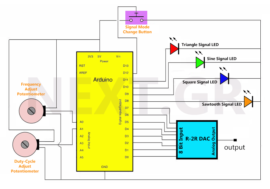
Once the circuit receives power, all variables are initialized, and the loop function runs continuously. Initially, all LEDs are off, and there is no output signal. Pressing the signal switch activates the first LED, indicating the output signal. The...
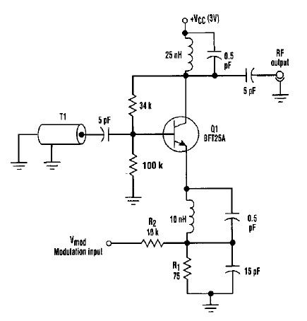
This varactorless high-frequency modulator electronic project must be powered by a simple DC 3-volt power source, such as a 3-volt battery. Traditionally, high-frequency oscillators are frequency-modulated using a varactor. However, varactors typically require a significant voltage change to achieve...
The TDA2030 is a monolithic integrated circuit in a Pentawat® package designed to function as a Class AB audio amplifier. It typically delivers up to 14 watts of output power (with a distortion rate of 0.5%) at 14V with...
To manufacture large quantities of products, a manufacturing system or process is essential. This process can be categorized as either open-loop or closed-loop. In an open-loop system, variables are controlled manually, whereas in a closed-loop system, they are controlled...
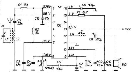
This AM radio receiver circuit utilizes the TDA1083 radio IC, which is suitable for constructing a simple medium frequency (MF) band radio. The schematic operates within a frequency range of 300 kHz to 3 MHz. The circuit is straightforward...
Warning: include(partials/cookie-banner.php): Failed to open stream: Permission denied in /var/www/html/nextgr/view-circuit.php on line 713
Warning: include(): Failed opening 'partials/cookie-banner.php' for inclusion (include_path='.:/usr/share/php') in /var/www/html/nextgr/view-circuit.php on line 713