
Flickering Light II

This circuit utilizes a combination of light-emitting diodes (LEDs) and a microcontroller to create realistic flame effects. The design typically includes multiple LEDs of different colors to represent the varying hues of fire. For instance, red, orange, and yellow LEDs can be arranged in a way that mimics the flickering and glowing nature of flames.
A microcontroller, such as an Arduino or similar, is programmed to control the brightness and the flickering pattern of the LEDs. This is achieved by using pulse-width modulation (PWM) to adjust the intensity of each LED. The microcontroller can be programmed with different algorithms to simulate the behavior of flames. For example, it can vary the brightness in a random manner to create a more natural and dynamic appearance.
Power supply considerations are also critical for this circuit. A suitable power source, such as a battery or an AC-to-DC adapter, must be selected to ensure that the circuit operates efficiently without overheating. Additionally, resistors should be included in the circuit to limit the current flowing through the LEDs, preventing damage and ensuring longevity.
In terms of assembly, the circuit can be laid out on a breadboard for prototyping or soldered onto a printed circuit board (PCB) for a more permanent solution. Proper heat management should be considered, especially if the circuit is intended for extended use.
Overall, this flame simulation circuit is versatile and can be adapted for various applications, including decorative lighting, stage effects, or educational demonstrations about fire behavior.Regardless of whether you want to effectively imitate a house fire, a campfire, or light from welding, the circuit described here fills the bill without u.. 🔗 External reference
Related Circuits
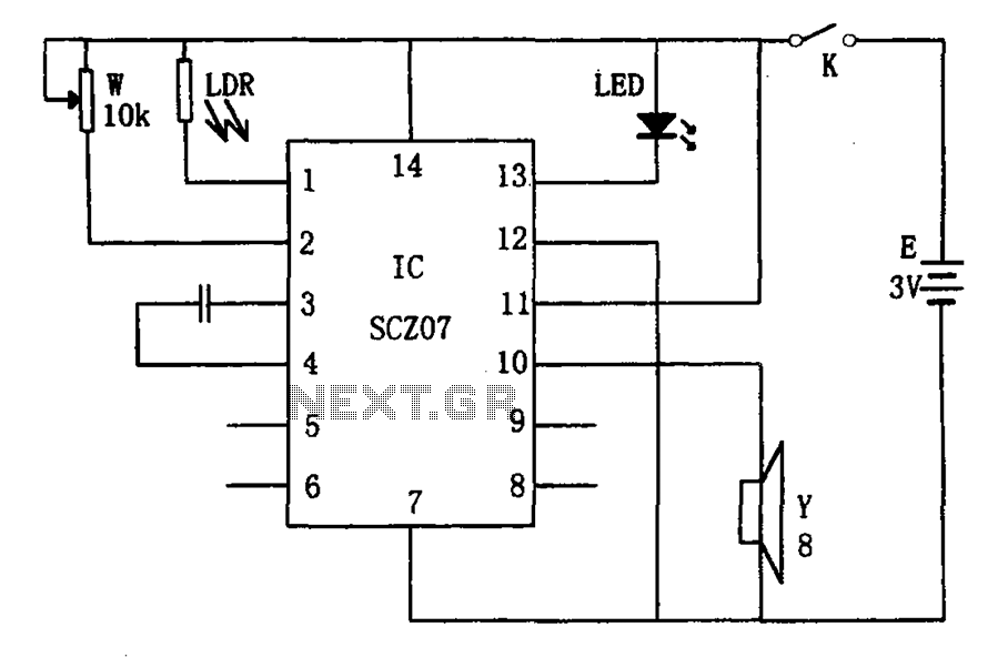
The weak light alarm circuit is illustrated in the figure. The oscillator circuit's core component is the SCZ07. The input signal is controlled by a potentiometer (W) and the output signal is processed by a photoresistor (LDR). The circuit...

Sun tracking systems significantly enhance the efficiency of photovoltaic (PV) arrays and are crucial for concentrated PV systems. This document discusses a light tracking servo model designed to simulate the movement of a PV array. A mathematical model is...

The circuit diagram presented is for an IC controlled emergency light with a charger, functioning as a 12V to 220V AC inverter circuit. Key features include automatic activation of the light during a mains failure and a battery charger...

In certain applications, the current from a non-rectified voltage power supply circuit is insufficient. A light-emitting diode (LED) rectifier circuit can be employed to address this issue, serving as a power indicator. It is important to ensure that the...

This light sensor switch circuit enables the automatic activation of a lamp when ambient light levels are low (such as during nightfall) and keeps the lamp illuminated for a specified duration. When transistors T4 and T5 are activated, the...

The Darlington circuit is a double-clamp touch switch circuit that features a touch-sensitive sheet and operates with a 20V AC mains supply through an isolated power transformer, ensuring relative safety. Once powered, a 20V optional AC transformer (T) is...