
Eight outputs flash circuit diagram
This lighting control circuit is designed to provide a dynamic visual experience by synchronizing light flashes with audio signals. The LP188 flash ICs are the core components that facilitate this synchronization, allowing for a variety of flash patterns based on the audio input's amplitude. The circuit's operational range of 9V to 18V ensures compatibility with various power sources, making it suitable for different applications, including decorative lighting and event displays.
The audio amplifier's gain of 100dB allows it to effectively amplify low-level audio signals, ensuring that even subtle changes in the audio input can influence the flash frequency. The VCO's responsiveness to the audio signal's amplitude enables the circuit to produce a wide range of flash speeds, enhancing the visual impact of the lighting.
The selection of components, such as the resistors and capacitors, is critical for achieving the desired performance. The choice of Rx and Cx values directly affects the modulation rate and oscillation frequency, allowing for fine-tuning of the circuit's response to audio signals. The ability to customize flash patterns by paralleling outputs provides flexibility in design, enabling the creation of unique lighting effects tailored to specific applications.
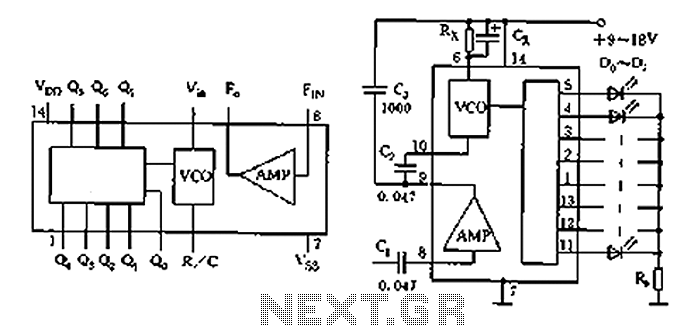
Overall, this circuit exemplifies an innovative approach to integrating audio and visual elements, making it a valuable tool for creating engaging and interactive lighting displays. As shown in the circuit is a state of the flash output can change the speed of lighting control circuit according to the strength of eight timing of the audio signal. Circuit p rinciple: This circuit uses eight flash IC assembled LP188, LP188 uses 14-pin dual in-line plastic package. Its internal logic diagram shown in a, the circuit of 14 feet and 7 feet, respectively positive and negative power supply, 6 feet R/C is a voltage controlled oscillator input, 8 feet and 9 feet for the input and output of audio amplifier, Q0 ~ Q5 are eight flash output.
Circuit power supply voltage is 9 ~ 18V; audio amplifier gain of 100dB, audio amplifier input signal 0.5Vpp, voltage controlled oscillator input signal 1.5Vpp, flash Each output current greater than 20mA, voltage controlled frequency modulation rate 1-20 times. Figure b flash circuit coupled from the C1 to the audio signal amplifier and control the voltage-controlled oscillator (VCO) the oscillation frequency.
Input signal amplitude, fast oscillation frequency, otherwise slow. Modulation rate of between 1 to 20 times, the oscillation frequency is determined by Rx and Cx, Rx can be 470k Euro ~ 1.5M Europe, Cx at 1 ~ 2uF value between the current limiting resistor R limit the size of the current work in every way. Flash shape can be edited as desired group, whose output can also be used in parallel, if Q0Q4, Q1Q5, Q2Q6, Q3Q7 output terminal in parallel, can be constructed four decorative fun flash circuit.
Component selection: D0 ~ D7 optional ordinary luminous tube, R0 ranging between 10 to 30 ohms.
Related Circuits
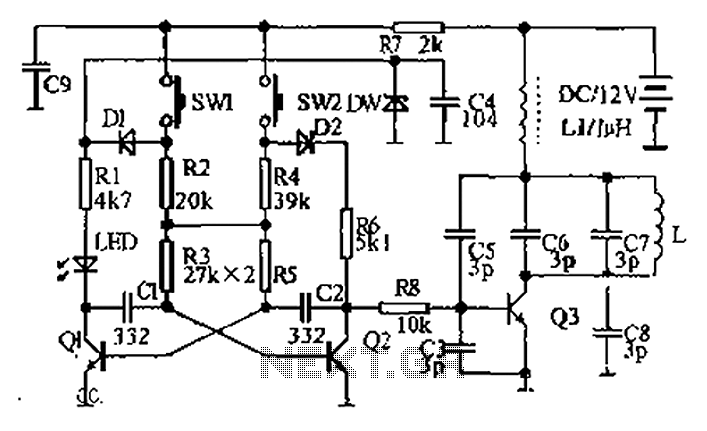
The circuit diagram illustrates a dual radio remote control switch system. The transmitter section features Q3, which generates a high-frequency carrier signal, while Q1 and Q2 form the oscillator circuit. Pressing switch SW1 results in an oscillation frequency of...
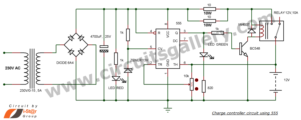
This is a simple DIY charge controller schematic created in response to a request from one of the readers on our Facebook page. The primary component of this automatic battery charger circuit is a 555 timer, which compares the...
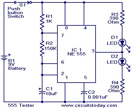
This schematic requires clarification. It is assumed that pin 2 is connected by a wire to pin 6, although this connection appears to be unclear. The circuit in question involves a schematic where pin 2 and pin 6 are interconnected....
This circuit utilizes a relay to control a water pump, enabling automatic level management of a water reservoir or well. The shorter steel rod functions as the "water high" sensor, while the longer rod serves as the "water low"...
These two projects, Wah and Fuzz, are the results of a modification to a Morley dual channel volume control pedal that one of my sons suggested I undertake as he had no use for the volume unit but thought...
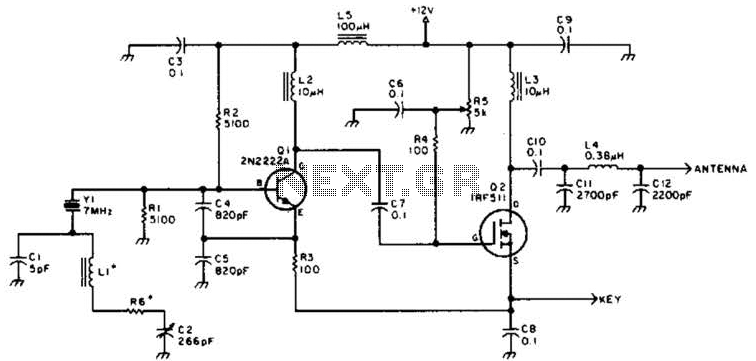
A DSB transmitter is significantly less expensive to construct compared to an SSB transmitter since it does not require filters or phasing networks. This circuit can generate an output of up to 1 watt on the 10-meter band. The...