
confocal sync control
The control circuit for the scanning microscope is designed for precision and adaptability, featuring a comprehensive integration of various components that work harmoniously to achieve high-resolution imaging. The CRS Controller board is pivotal in generating the SLC, which synchronizes the mirror's oscillation with the scanning process. The adjustment of the mirror's position through the R48 potentiometer allows for fine-tuning, ensuring accurate alignment with the SLC.
The horizontal sync signal generated by the SLC is crucial for coordinating the frame grabber's line acquisition. The inclusion of the CD4050 buffer ensures that the signal maintains integrity and sufficient current to drive the Raven board effectively. The use of the 74LS221 monostable multivibrator enhances the signal quality by producing fast pulse signals, optimizing data capture efficiency.
The frequency doubling accomplished by the CD4070 IC is essential for maintaining synchronization during the vertical scanning process. This doubling allows for the collection of two horizontal lines of data for each mirror oscillation, effectively increasing the data acquisition rate and enhancing imaging capabilities.
The 12 Stage Counter (CD74HCT4040E) provides a robust method for tracking line counts, with its binary output directly influencing the digital-to-analog conversion process. The AD7393 AN converter transforms the binary count into a saw-tooth waveform, which is critical for driving the vertical scan mirror. The saw-tooth waveform's characteristics can be adjusted based on the selected line count, ensuring optimal performance across various imaging scenarios.
The operational amplifiers (LT1012) employed for offset control and saw-tooth amplification play a vital role in centering the saw-tooth waveform around zero volts and controlling the scan height. This dual functionality allows for precise adjustments in the imaging process, accommodating different magnification requirements.
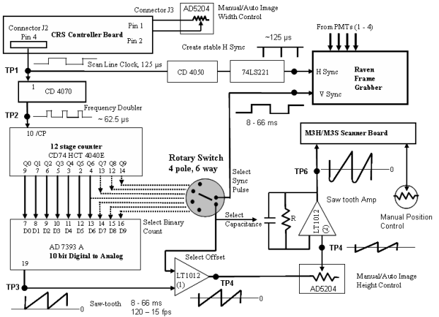
Overall, the control circuit exemplifies an intricate design that combines various electronic components to facilitate advanced scanning microscopy, highlighting the importance of synchronization, signal processing, and precise control in achieving high-quality imaging results.Before attempting to build the control circuit, it is recommended that the function of each part the circuit is understood. The schematic below shows the basic functions only. CRS Controller board: The key synchronization signal or Scan Line Clock (SLC) for the scanning microscope is generated automatically by the CRS Controller board.
The rising edge of the square pulse of the SLC indicates the start of each sinusoidal oscillation of the CRS mirror. This is available on pin 4 of connector J2. The exact position of the CRS mirror relative to the timing of the SLC can be adjusted with a potentiometer on the CRS board (R48).
R48 should be set to 0 to align the SLC with the 0 position of the mirror. The factory setting is for a 5 µsec delay. The angle of the CRS mirror oscillation (smaller angle = shorter scan distance = larger magnification) is controlled by an input voltage at pin 2 of connector J3 on the CRS board. This voltage may be manual regulated by a front panel potentiometer or by computer-controlled digital potentiometer (AD5204) for automatic zoom control.
Horizontal Sync Signal: The SLC from the CRS board serves to form the horizontal sync signal to coordinate the line-acquisition by the frame grabber (Raven). Before reaching the Raven frame grabber the H sync signal is processed via a CD4050 to provide sufficient current to drive the Raven board.
In addition, the signal is processed via a monostable multi-vibrator with Shmitt-trigger (74LS221) to generate a fast pulse signal. The Raven temporarily stores the data captured from a forward and reverse scan as a single line in image memory before processing.
Frequency Doubler (CD4070): The strategy for using an oscillating mirror is to avoid the requirement for a fast fly-back of the scanning mirror and to utilize the symmetrical reverse scan to collect image data. The result of this approach is that 2 horizontal lines of data can be collected for each full mirror oscillation.
Consequently, the synchronization signal needs to be doubled to track the vertical progress. The CD4070 IC creates a pulse at the positive and negative edge of the scan clock to double the clock frequency. 12 Stage Counter (CD74HCT4040E): Each sync pulse entering the counter serves to increment a line-count and this is digitally represented as a binary scale on the output lines (using Q0 - Q9).
Counts of 128, 256, 512 and 1024 are indicated by HIGH signals at Q6, 7, 8 and 9, respectively. Depending on the count position selected with the rotary switch, a HIGH signal representing the vertical sync signal is sent to the frame grabber to advance the image. Digital to Analog Converter (AD7393 AN): The binary output of the counter is instantly feed into a 10 bit digital-to-analog converter.
This results in an output voltage at pin 19 with a saw-toothwaveform that progressively increases with each input pulse. The saw-tooth ranges from 0 volts with a full scale referenced to 5 volts (count of 1024). This saw-tooth will drive the the motion of the vertical scan mirror (M3H/S). The required line count is selected by the rotary switch which functions by connecting addition binary lines to the converter.
A reset is not required for values of 128, 256, or 512 because these values divide exactly into 1024 and reset automatically during sequential counting. Offset Control (Op Amp 1, LT1012): To center the saw-tooth around zero volts (and to center the mirror scan at all image acquisition rates) the saw-tooth is processed by an op amp configured as a difference amplifier.
The appropriate fixed difference voltage for each line-count (2. 5 v x line-count/1024) is supplied via the rotary switch. Saw-tooth Amp (Op Amp 2 LT1012): The magnitude of the saw-tooth signal controls the height of the vertical scan (smaller scan = higher magnification). The magnitude is controlled by 2 processes: a manual or digital potentiometer (AD5204) varies the saw-tooth v
🔗 External reference
Related Circuits
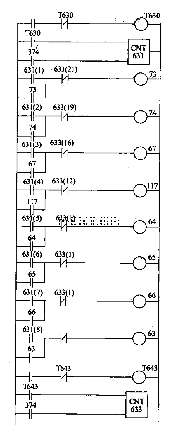
Based on the system characteristics, a drum controller is utilized to meet the specified requirements, with the design of the ladder as illustrated in the accompanying figure. 1) C631 and C633 function as a drum controller, counting pulses generated...
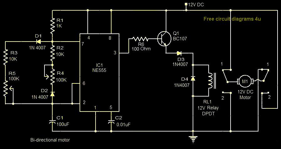
This circuit illustrates a bi-directional motor control circuit utilizing the NE555 integrated circuit (IC). Features include a 12V DC power supply, with the IC employed to control relay RL1. The bi-directional motor control circuit designed with the NE555 IC allows...
This circuit was provided by Mr. Guy Bocquillon from France. Now retired and in his seventies, Mr. Bocquillon remains active in his hobby, and his contributions and support are greatly appreciated. The notes on the schematic are in French,...
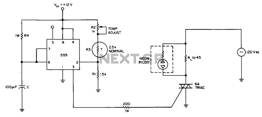
The internal comparator of the 555 timer, combined with a thermistor, creates a low-cost temperature controller. Resistor R2 establishes the temperature trip point. The 555 timer is a versatile integrated circuit widely used in various applications, including timers, oscillators, and...
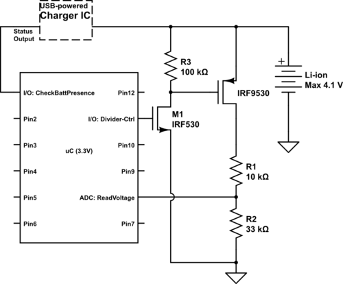
Currently using the PIC24FJ128GA010, there is a plan to utilize an Input/Output port to connect a 4.2 V LiPo battery and monitor the voltage to ensure it does not drop below 3.7 V. It is advised to avoid digital...
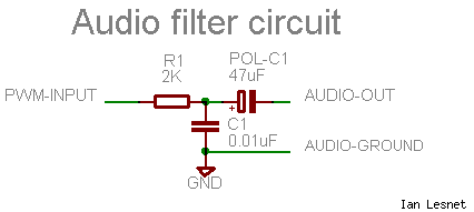
The signal from the MSP430 PWM pin is not suitable for directly driving a speaker or amplifier. To improve the signal quality, it is advisable to process it through a low-pass filter, which smooths out the sharp edges of...
Warning: include(partials/cookie-banner.php): Failed to open stream: Permission denied in /var/www/html/nextgr/view-circuit.php on line 713
Warning: include(): Failed opening 'partials/cookie-banner.php' for inclusion (include_path='.:/usr/share/php') in /var/www/html/nextgr/view-circuit.php on line 713