
temperature control circuit 555 ic
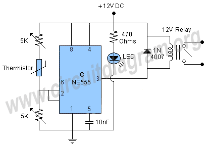
The circuit design features a thermistor, which is a temperature-sensitive resistor that changes its resistance with temperature variations. This component is critical for accurately detecting temperature changes in the environment. The two 5K variable resistors allow for fine-tuning of the circuit's sensitivity and threshold, enabling the user to set the precise temperature at which the relay will activate.
When the temperature reaches the predetermined level, the resistance of the thermistor will change, which in turn affects the voltage across the variable resistors. This change in voltage is used to trigger the relay, which can control a larger load, such as a heater or fan, based on the temperature reading.
The 1N4007 diode is connected in parallel with the relay coil to protect the circuit from voltage spikes that occur when the relay is de-energized. This back EMF can potentially damage other components in the circuit. The diode provides a path for the current generated by the collapsing magnetic field of the relay coil, thereby safeguarding the integrity of the circuit.
Powering the circuit with a 12-volt supply allows for a robust operation, but the circuit's design is also adaptable for a 6-volt power supply. In this case, it is essential to ensure that a relay rated for 6 volts is employed to maintain proper functionality. This flexibility in power supply options enhances the versatility of the circuit for various applications.A Thermistor is used in the circuit for sensing the heat and two 5K variable resistors are used to adjust the circuit to activate the relay on the desired temperature. The purpose of using the 1N4007 diode across the relay is to limit the back EMF of the relay coil. The circuit can be operated with a 12 volt battery or power supply but you can als o operate it with 6 volt battery or power supply but make sure to use a 6 volt relay also. 🔗 External reference
Related Circuits
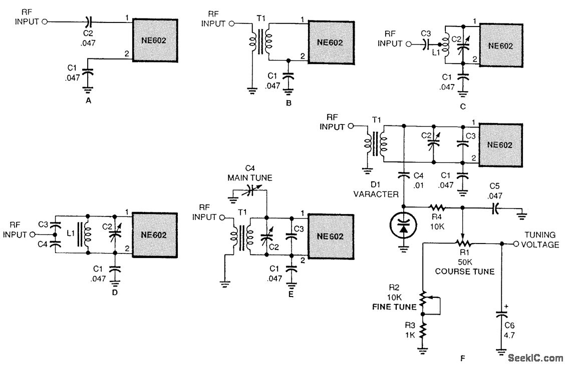
There are several methods to input a signal into the NE602. Simple untuned approaches (a and b) are viable. For tuning to a specific frequency, an LC resonant circuit with ungrounded trimmer capacitors (c and d) or grounded variable...
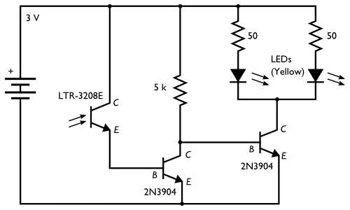
Here is an inexpensive electronic circuit that can be built to place in a Jack-o'-lantern. It provides power to drive a few LEDs at night and automatically turns them off during the daytime. This is a simple and automatic...
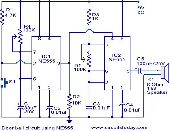
The primary components of this doorbell circuit are two NE555 timer integrated circuits (ICs). When switch S1 is pressed momentarily, the loudspeaker emits a bell tone for the duration determined by the monostable multivibrator configuration around IC1. Pressing switch...
1 kHz RC phase shift oscillator circuit The 1 kHz RC phase shift oscillator circuit is designed to generate a continuous sine wave output at a frequency of 1 kHz. This circuit typically utilizes a combination of resistors and capacitors...
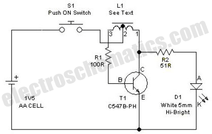
This simple LED driver circuit allows the operation of up to seven LEDs using a single NiMH (Nickel Metal Hydride) AA cell. The circuit generates voltage pulses. The LED driver circuit is designed to efficiently power multiple LEDs while maintaining...

This is a stereo power amplifier circuit that operates at up to 22W per channel, resulting in a total output of 2x22W. A few external components are required to support the main component, the TDA1554. A heatsink on the...