
A dark detecting circuit for your jack lantern
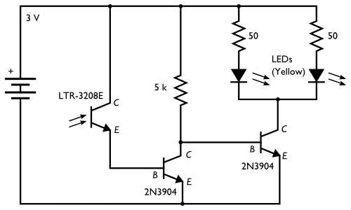
The circuit operates on a simple principle of light detection and switching. The phototransistor, being sensitive to infrared light, allows the circuit to respond to ambient light conditions effectively. The Darlington pair configuration enhances the sensitivity of the circuit, making it capable of detecting lower light levels, such as those found in shaded areas or during twilight. The use of the 2N3904 transistors allows for efficient switching of the LED load, providing a means to illuminate the Jack-o'-lantern in the dark while conserving battery power during the day.
In terms of component selection, the LTR-3208E phototransistor is chosen for its responsiveness to infrared light, which is particularly useful in outdoor settings where various light sources can affect circuit performance. The 2N3904 transistors are standard NPN transistors that are widely available and suitable for low-power applications. The resistors used in the circuit play a crucial role in setting the biasing conditions for the transistors and limiting the current through the LEDs to prevent damage.
This circuit can be adapted for various applications beyond a Jack-o'-lantern, including decorative lighting for gardens or pathways, where automatic operation based on ambient light is desired. The straightforward design and use of commonly available components make it an excellent project for both beginners and experienced electronics enthusiasts.Here`s an inexpensive electronic circuit that you can build to put in your Jack-o`lantern. It provides power to drive a few LEDs at night, and automatically turns them off during the daytime. It`s a simple and automatic dark-detecting circuit that you can use to for your very own photosensitive pumpkin. While the minimalist circuit is marvelously compact and simple, it is limited both in terms of sensitivity, LED driving capability, and extensibility. It can drive a single red or yellow LED from a lithium coin cell but that`s it and it requires fairly bright light (e.
g. , direct sunlight) to turn off the LED. So our new dark-detecting circuit is only almost as compact or simple, but is much more sensitive, and is capable of driving several bright LEDs for your Jack-o`lantern. We`ll get started with the basic circuit construction, using two LEDs for eyes, and then look at how to modify the circuit to use more or different types of LEDs.
The photosensitive element is a phototransistor. We use type LTR-3208E here; it`s an infrared-sensitive type with a dark lens. Being IR sensitive it sees sunlight and incandescent lights, but not fluorescent or (most) discharge lamps- it really will come on at night. The typical "saturation" current of this type of phototransistor is only of order 1 mA, which means that under conditions much less bright than sunlight, we get much less than 1 mA of output current.
To increase the sensitivity of our pumpkin enough to detect indirect daylight lighting- not just direct sunlight- we use the phototransistor as one element of a Darlington pair. When daylight is detected, the phototransistor turns on (just a little bit), which turns on the first 2N3904, which pulls the base of the second 2N3904 to ground, and preventing the LEDs from turning on.
When it`s dark out, no current can flow through the phototransistor or the first 2N3904, which allows the base of the second 2N3904 to be pulled high through the 5 k transistor, which turns on the LEDs through that transistor. As drawn here, the circuit draws 0. 5 - 1 mA (depending on ambient light) when it`s daytime and up to about 35 mA when driving the two LEDs at night.
(If your LEDs are superbright types, you might want to cut down on brightness and power usage by using larger load resistors. ) The photosensitive part of the circuit is independent of what`s actually driven by the second 2N3904, so you can change the load applied there easily.
Our circuit is drawn with two LEDs, each with its own load resistor, however you can actually use 1-4 parallel LEDs if each has its own load resistor. ] A good place to start playing with a circuit like this is on a solderless breadboard. For the most part you can follow the circuit diagram. You`ll need to know that on our type of phototransistor the flat side that denotes the collector pin (C on the diagram).
Also, the pins of the 2N3904 are called (left-to-right) Emitter, Base, Collector (E, B, and C on the diagram), when viewing it from the front such that you can read the writing. On the LEDs, the side with the short lead and/or flatted faced on the lens is generally the cathode, which is the side with the flat bar in the diagram.
From there, we constructed the same circuit on a small piece of plain perfboard. There are three twisted wire pairs going off from this little board to (1) the photosensor and (2, 3) the LEDs. (There are really just the two transistors and three resistors on the board the resistor-looking thingies with one black stripe are just fancy wire jumpers.
) Here`s the whole setup with the phototransistor and LEDs visible at the ends of their wire leads. We use the long leads to be able to put the LEDs and sensor exactly where we want them in the pumpkin. We`ve protected the end of the leads with heat-shrink tubing. (No use shorting out our circuit with pumpkin goo. ) The circuit board is strapped to the 2 x AA battery box with a 🔗 External reference
Related Circuits
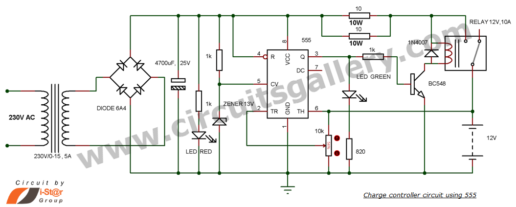
This is a simple DIY charge controller schematic created in response to a request from one of the readers on our Facebook page. The primary component of this automatic battery charger circuit is a 555 timer, which compares the...
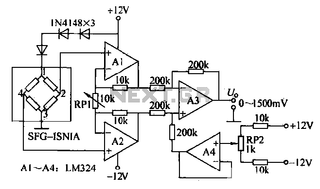
This is a measurement circuit designed to measure forces ranging from 0 to 1500 grams, producing an output voltage of 0 to 1500 millivolts (mV) with a sensitivity of 1 mV per gram. The circuit is powered by a...
The purpose of this circuit is for research and education. Assistance is sought in acquiring components for simple RF circuits, as well as tutorials or schematics. The requester is facing challenges in locating quality resources for beginner-level RF circuit...
The gain of the single-stage virtual earth amplifier IC1 is determined by the drain-source resistance of the field-effect transistor (FET). Resistors R1, R2, and R3 linearize the FET's voltage-current characteristic. A control voltage is derived from the output signal...
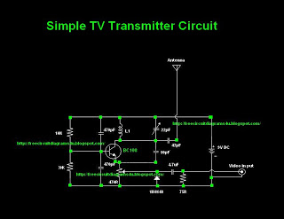
Many individuals inquire about TV transmitters. This document provides a useful circuit diagram that enables signal transmission over distances of 75 to 100 meters. The circuit diagram is not original but was provided by a colleague. Contributions of circuit...
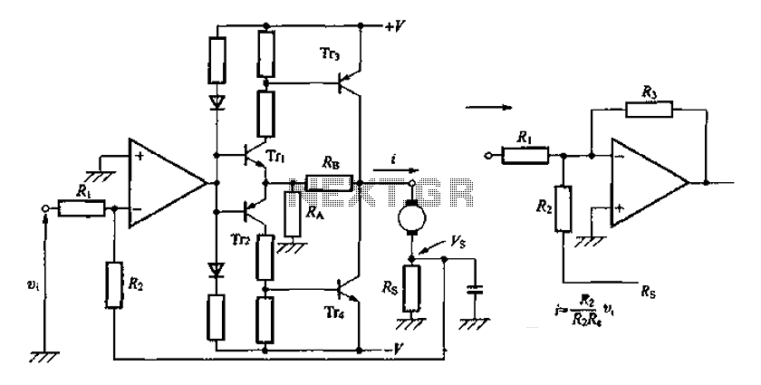
A discrete transistor current control circuit diagram. The discrete transistor current control circuit is designed to regulate the flow of current through a load by utilizing a transistor as the primary control element. This circuit typically consists of a few...
Warning: include(partials/cookie-banner.php): Failed to open stream: Permission denied in /var/www/html/nextgr/view-circuit.php on line 713
Warning: include(): Failed opening 'partials/cookie-banner.php' for inclusion (include_path='.:/usr/share/php') in /var/www/html/nextgr/view-circuit.php on line 713