
Voltage Controlled LFO

The Low-Frequency Oscillator (LFO) circuit operates by utilizing a combination of analog components to create a stable and adjustable waveform output suitable for modulation in various electronic applications. The core of the circuit consists of a linear voltage to logarithmic current converter (U1), which translates the input voltage into a corresponding current that can be manipulated further in the circuit. The transconductance amplifier (U3-A) acts as the primary control element, regulating the frequency of oscillation based on the current flowing into its collector.
The integrator (U2-A) plays a crucial role in shaping the output waveform. By integrating the current from the transconductance amplifier, it generates a ramp signal that alternates between rising and falling states. The comparator (U4-A) monitors this ramp signal and toggles its output state based on predefined voltage thresholds, effectively creating a triangle wave output.
The frequency range of the oscillator is notably broad, allowing for low-frequency applications where modulation effects can be subtle yet impactful. The design facilitates user adjustments, such as the trim pot (R25), which fine-tunes the symmetry of the triangle waveform, ensuring that the output remains consistent and usable for further processing.
Incorporating feedback mechanisms, such as the hysteresis provided by R63, helps stabilize the output against noise and variations in the input signal, which is critical for maintaining reliable operation in practical applications. The output can be used to drive other components in a modular synthesis setup or integrated into larger systems requiring modulation signals.
This LFO design exemplifies the principles of analog synthesis, where careful consideration of component selection, circuit topology, and user control interfaces culminate in a versatile tool for sound design and modulation. Proper assembly and calibration, as outlined in the documentation, will ensure optimal performance and reliability in various electronic projects.This is a nice LFO for all of your modulation needs. The frequency can be voltage controlled to add a new dimension to your sound palette. The pulse width of the rectangle wave can be varied between approximately 10% and 90% again lending variability to the modulation capabilities of this LFO. Voltage control can be used to vary the pulse width as well. If you power your circuits with +/-15 volts then observe the recommended changes that are noted on the schematic. I recommend a complete review of this page before buying a board. U1 and associated components comprise a linear voltage to log current converter. The current flowing into the collector of Q2 controls the current flowing from the bias input of U3-A transconductance amp to ground via Q3.
The transconductance of U3-A is used to control the frequency of the oscillator. U2-A and associated components comprise an integrator. When current flows into U3-A`s output the integrator ramps up and when current flows out of U3-A`s output the integrator ramps down. When the integrator`s output goes above the threshold of comparator U4-A and associated components it`s output goes high (to near +V).
The output of U4-A is fed to the non-inverting input of U3-A transconductance amp. While U4-A`s output is high current flows out of U3-A`s output and the integrator ramps down until the voltage at the input of U4-A goes low enough to overcome the hysteresis provided by R18 and it`s output goes low. When this happens the comparator starts to ramp up again and thus we have a triangle wave at the output of U2-A.
The amp bias of U4-A is controlled by the current generated by the linear voltage to log current convertor. This controls the current that flows in and out of U4-A and thus the frequency of the oscillator. The oscillator`s frequency can be varied from super low (a cycle takes over two minutes) to about 600 HZ.
Don`t hold my feet to the fire on exact range. When I turn it all the way down and listen to it`s effect on an oscillator, I can just discern the change in frequency as the voltage ramps up or down. I insured that at the lowest setting the comparator still trips high and low. You could probably increase C11 if you want it to go lower. The frequency goes up with higher control voltage and down with lower control voltage I do not advertise that the oscillator tracks well and will give you 1V per octave.
In my applications of low frequency oscillators I do not need this capability. IF YOU NEED 1V/OCT TRACKING, THEN THIS IS NOT THE VC-LFO FOR YOU. I don`t mean to shout with the bold caps, I just don`t want people to miss that point. Trim pot R25 is used to balance the current flowing during the high and low periods of U4-A. With the coarse frequency set to about mid-way and while viewing the output of U2-A adjust R25 until the symmetry of the triangle waveform is as perfect as you can get it. You can use the scope`s non-calibrated horizontal sweep adjust and horizontal position controls to help get one cycle displayed properly too.
The symmetry of the triangle waveform will affect all of the other waveforms and is thus very important to get right. Use the output of U4-A to trigger the scope so that one triangle cycle is displayed on the scope (low to high to low OR high to low to high).
The goal is to get the wave to start at the left end of the graticule, peak (or valley) at the exact center of the graticule, and then end at the right end of the graticule. I find this view useful when I`m populating the board. I don`t have to go back and forth from the designator to the value. It speeds up construction. Click the "Larger GIF" link and print the image as landscape. C12 needs to have a 4. 7 meg resistor (R63) placed in parallel with it. This resistor adds a necessary bit of hysteresis to the square wave comparator. Without it you will get chatter (rapid oscillation) as the ramp wave approaches U6-A`s threshold. I sugge 🔗 External reference
Related Circuits
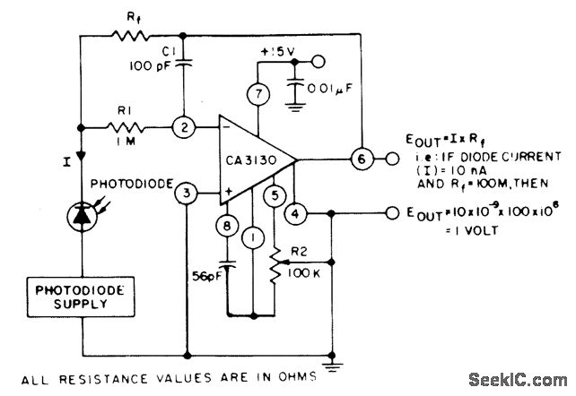
The circuit employs three CA3130 BiMOS operational amplifiers in an application that is sensitive to sub-picoampere input currents. It generates a ground-referenced output voltage that is proportional to the input current flowing through the photodiode. The described circuit utilizes three...
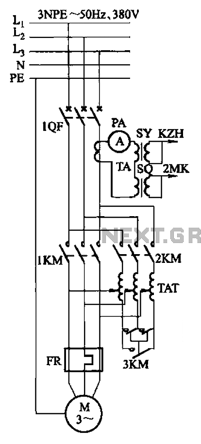
Autotransformer voltage starting, with an adjustable starting time of 30-60 seconds. It includes the SDJ electrode liquid level sensor of HJ-13 type, a pump control system box of HKD-21B type, 1MK level modules adopted by HKG-1SG type, 2MK start...
The LM3361A features a complete narrowband FM demodulation system that operates at supply voltages of less than 2V. The device includes several blocks such as an oscillator mixer, FM IF limiting amplifier, FM demodulator operational amplifier, scan control, and...
This is a low-dropout (LDO) regulator circuit, constructed using only a single PNP transistor. This circuit is directly related to load current. At very low... The low-dropout (LDO) regulator is a crucial component in power management systems, providing a stable...
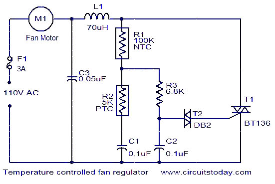
The function is designed to automatically control the speed of a fan based on the temperature. Components include a BT136 Triac, capacitor, resistor, relay, and fan motor. The circuit employs a temperature sensing mechanism to monitor ambient temperature levels. A...
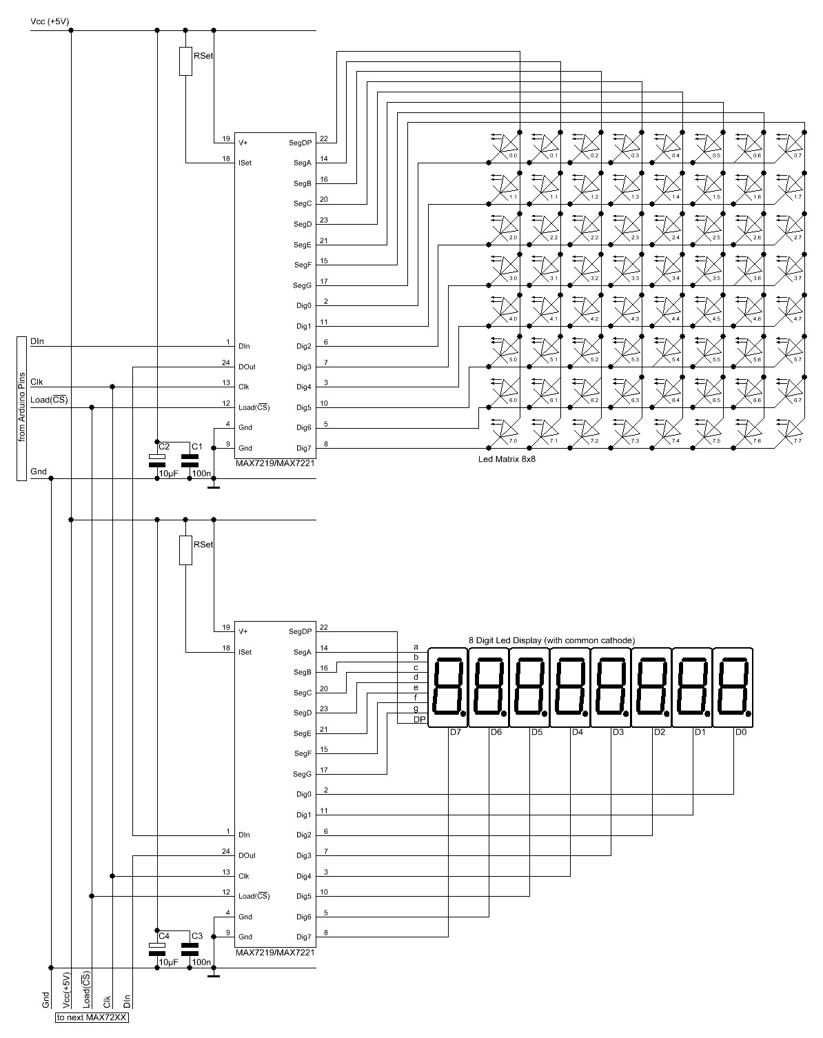
The Arduino website provides comprehensive documentation on connecting LEDs to the Arduino using the MAX7221. A specific set of components is required for this setup. The MAX7221 is a versatile LED driver that enables the control of multiple LEDs through...