
Temperature Conversion circuit
The Excelitas TPS 1T 0134 OAA060 thermopile sensor represents a significant advancement in thermal detection technology, integrating a built-in operational amplifier to enhance its performance. The self-contained nature of this module simplifies integration into various applications, particularly where accurate temperature measurements are crucial. The sensor's ability to convert thermal radiation into a voltage output facilitates its use in a range of environments, with the pre-calibrated options providing immediate usability for temperature readings.
In practical applications, the selection of an appropriate power supply is critical. The recommended 78L05 voltage regulator, paired with a standard 9-V battery, ensures that the sensor operates within its specified voltage range, thereby maintaining accuracy and reliability. The operational characteristics of the sensor can be further optimized by utilizing high-quality resistors in the voltage divider circuit, ensuring that the output remains stable and within the input limits of connected data loggers.
The implementation of a unit-gain non-inverting amplifier serves to buffer the output from the A2TPMI, providing the necessary impedance matching to the data logger. This configuration not only protects the sensor from potential loading effects but also enhances the fidelity of the temperature readings. Calibration procedures, involving direct voltage measurements, are essential to establish a precise correlation between the sensor output and the amplified signal, allowing for accurate temperature determinations in various applications.
Overall, the Excelitas TPS 1T 0134 OAA060 thermopile sensor, with its robust design and integrated features, presents a versatile solution for thermal measurement needs across diverse fields, including environmental monitoring, industrial applications, and research initiatives.The Excelitas TPS 1T 0134 OAA060 thermopile sensor is a self-contained module with a built-in op amp. (We use the A2TPMI 334 OAA 60 designation in this document because that was the PerkinElmer part number when we purchased them.
Since then, PerkinElmer`s optoelectronics division has been sold to Excelitas ( and online searches will still bring up references to this device under the PerkinElmer name and part number. The TPS sensor is described by Excelitas as a "recent upgrade" to the TPMI sensors. It is possible that specifications for the TPS sensor ” and, in particular, the equation for converting voltage to temperature ” might be slightly different from the A2TPMI. ) These detectors sense thermal radiation, with spectral response as shown in the graph below. The units come in a variety of configurations, including units that are pre-calibrated for converting voltage to temperatures in °C.
The AT2PMI 334 OAA060 version produces a voltage output in the range of 0-4. 5 V, corresponding to a temperature range from -27 °C to 60°C. (Only the most extreme polar regions are likely to lie outside this range!) It is easy to check out the operation of an A2TPMI with a multimeter. It requires only a regulated +5V power supply, which can easily be provided with an IC voltage regulator (78L05) and a 9-V battery.
The circuit doesn`t require much power and even a carbon a 9-V battery (sometimes referred to as "heavy duty") widely available at two-for-$1 at dollar stores will last for a couple of days of continuous operation. Because of the chopper-stabilized op amp used in this device, there is a small high-frequency signal on the output, but it should be negligible for this application.
There are some potential problems using this device with a data logger. For most of our projects, we use 12-bit-resolution HOBO U-12 series data loggers. These loggers have an input impedance of only 10 k ©, but, the A2TPMI requires a minimum resistive load of 50 k ©. Also, the A2TPMI voltage output exceeds 2. 5 V for temperatures above 30 °C ” a surface temperature value that is often exceeded. The solution is to combine a passive voltage divider with a unit-gain non-inverting amplifier. Such a circuit can provide the A2TPMI with an acceptably high resistive loading. An op-amp-based unit-gain amplifier has a very high input impedance (so that the load on the voltage divider can be neglected) and a very low output impedance.
Such a circuit provides an appropriate interface between the AT2PMI and the U-12 logger. If the voltage is divided in half, it will never exceed the 0 ”2. 5 V range of the U-12 logger. This requires two equal resistors whose total value (R1 + R2) is at least 50k ©hm. If high-precision resistors are used, then the output from the unit-gain amplifier is just multiplied by 2 to do the temperature calculation shown above. If only 5% carbon film resistors are available, it is possible to test several samples to find two with very close to the same value.
It would also be possible to use a variable resistor, a "trim pot, " to adjust the divider so the output from the unit-gain op amp is exactly half the output from the A2TPMI. In any case, units should be calibrated by measuring the output voltage directly from the A2TPMI and the comparing it to the output from the op amp, to determine the precise relationship between the sensor output and the amplified output voltage.
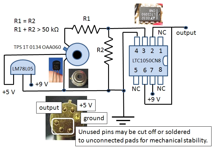
A circuit diagram is shown below. The op amp should be a high-quality low-noise device. We typically use the LTC1050 for these applications, although there are other pin-compatible choices. (The ubiquitous 747 op amp does not qualify as a "low-noise" alternative, even though it is pin-compatible.
) Because this is such a low-power circuit, A 78L05 5-V regulator in a TO-092 housing is the appropriate choice. The pins on the A2TPMI are fragile, and it might be a good idea to secure at least one of the unused pin
🔗 External reference
Related Circuits
This is an LM338-based power supply that is uncomplicated and easy to construct. It has been in use for an extended period without any issues. The circuit lacks a current adjustment feature, which has been addressed by incorporating an...
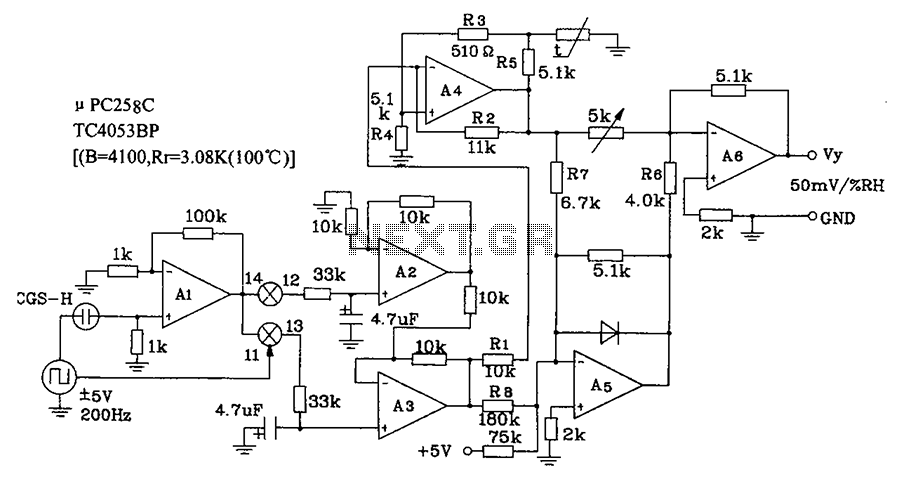
CGS-H ceramic humidity sensor constructed low humidity detection circuit diagram. The CGS-H ceramic humidity sensor is designed to detect low humidity levels within a specified range. This sensor operates on the principle of changes in capacitance that occur with variations...
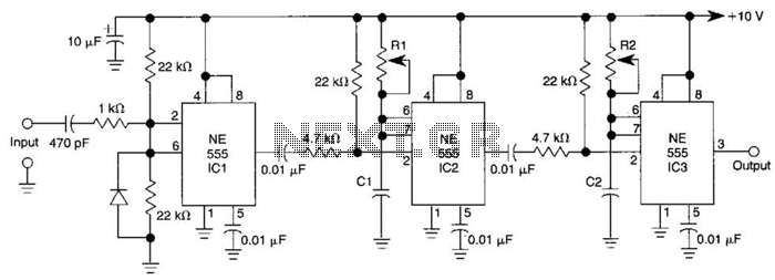
Three 555 IC timers are utilized in this circuit to create a simple delayed-pulse generator. IC1 functions as a waveform shaper to generate a rectangular waveform. IC2 generates a delaying pulse that triggers IC3 on the trailing edge of...
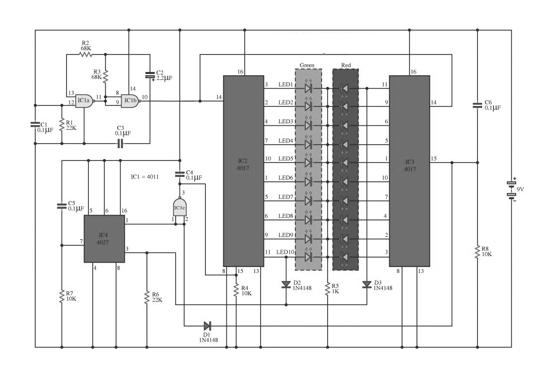
This circuit operates on alternating two colors using a 2-color LED with a built-in 3-pin configuration. It alternates the glow of each LED until the base, switching between two colors. The circuit comprises a NAND gate IC, two 10-counter...

The circuit utilizes a transistor (VT) and a voltage regulator (VSL) to create a constant current source, employing three regulators to enhance the performance of the regulator circuit. The described circuit employs a transistor (VT) in conjunction with a voltage...
This circuit automatically activates and deactivates a motorcycle's headlight, functioning independently of both the light and ignition switches, as long as the battery is fully charged. The initial stage employs a 220-ohm resistor and ZD1 to keep transistor Q1...
Warning: include(partials/cookie-banner.php): Failed to open stream: Permission denied in /var/www/html/nextgr/view-circuit.php on line 713
Warning: include(): Failed opening 'partials/cookie-banner.php' for inclusion (include_path='.:/usr/share/php') in /var/www/html/nextgr/view-circuit.php on line 713