
UJ-1 type potentiometer with a precision power supply circuit

The described circuit employs a transistor (VT) in conjunction with a voltage regulator (VSL) to establish a constant current source. This configuration is particularly advantageous in applications requiring stable current output regardless of variations in load or supply voltage. The inclusion of three regulators in the design serves to improve the overall performance and reliability of the circuit.
The first regulator in the series can be configured to provide a stable reference voltage, ensuring that the subsequent stages operate within their optimal parameters. The second regulator can be employed to regulate the output voltage, allowing for fine-tuning of the output current. The third regulator functions as a protection mechanism, safeguarding the circuit against overcurrent conditions and ensuring longevity and stability in operation.
In this configuration, the transistor (VT) acts as a control element, responding to the feedback from the voltage regulators to maintain a constant output current. The combination of these components results in a robust circuit capable of delivering precise current levels, making it suitable for various applications in electronic devices, such as LED drivers, battery chargers, and precision measurement instruments. The overall design emphasizes efficiency, stability, and protection, which are critical in high-performance electronic systems. By the transistor VT and regulator vsl etc. constant current source, and the use of three regulator, the regulator circuit therefore of high pulp.
Related Circuits
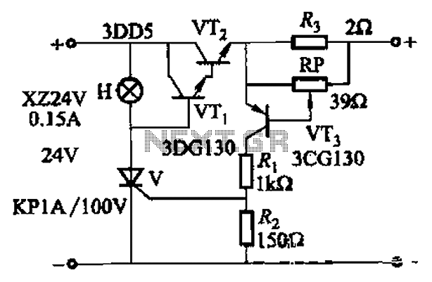
By adjusting Ro or RP, the current setpoint can be modified. The circuit illustrated in Figure 14-98 features overcurrent protection using a thyristor and transistors VTi and VT2, which immediately cut off the power when an overcurrent condition is...
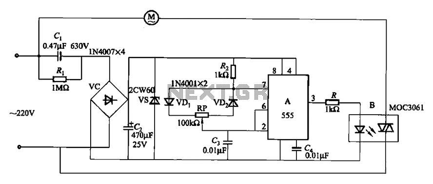
The circuit depicted in Figure 3-9 shares similarities with Figure 3-8, with the distinction that the zero-off MOC3061 type photoelectric coupler is directly connected to control the operation of the fan. The circuit utilizes the MOC3061, a phototransistor optoisolator, which...
A very useful talk-over circuit that can be utilized in radio stations, clubs, or any location where speaking over music is desired without the need for adjusting a potentiometer. The talk-over circuit is designed to automatically reduce the volume of...

The circuit diagram includes an input filter capacitor C1 and a primary clamp composed of VDz and VD1. The resistor R1 is connected to the control terminal. C2 serves as a bypass capacitor. The TOP414GC-S is connected in parallel...
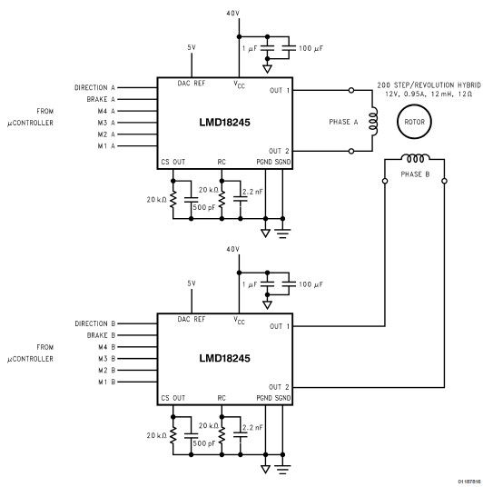
LMD18245 bipolar stepper motor driver circuit design using few electronic parts The LMD18245 is a versatile bipolar stepper motor driver designed to control stepper motors with precision and efficiency. This circuit utilizes a minimal number of electronic components, making it...
The Air Flow Sensor Circuit describes sensing air flow using the microcontroller PIC16C781. Air flow is detected by the cooling effect of air. The Air Flow Sensor Circuit utilizes the PIC16C781 microcontroller to effectively measure air flow by leveraging the...
Warning: include(partials/cookie-banner.php): Failed to open stream: Permission denied in /var/www/html/nextgr/view-circuit.php on line 713
Warning: include(): Failed opening 'partials/cookie-banner.php' for inclusion (include_path='.:/usr/share/php') in /var/www/html/nextgr/view-circuit.php on line 713