
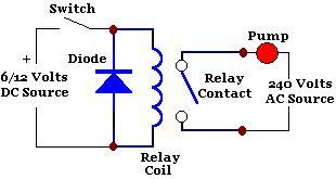
Light control relay control lamp
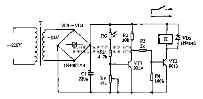
The circuit design effectively utilizes a step-down transformer to convert high voltage AC to a lower voltage DC, making it suitable for low-voltage applications. The diode bridge rectifier ensures that the current is converted from AC to DC, while the filter capacitor smooths out any fluctuations in the output voltage, providing a stable 12V DC supply.
The light control mechanism is primarily based on the behavior of the light-sensitive resistor RG. Under bright conditions, RG's low resistance allows current to flow through VT1, keeping it in a conductive state. This results in a low voltage at the collector of VT1, which in turn keeps VT2 off. As a result, the relay remains deactivated, and the connected lighting system does not operate, conserving energy during daylight hours.
Conversely, as ambient light diminishes, RG's resistance increases, leading to a drop in the base potential of VT1. This transition causes VT1 to turn off, allowing the collector voltage to rise. Consequently, VT2 is activated, energizing the relay and closing the contacts, which powers the lamp.
The adjustability provided by resistor RP allows for fine-tuning of the circuit's sensitivity to light levels. By modifying the resistance value of RP, the threshold at which the circuit transitions from off to on can be altered, enabling the system to adapt to varying ambient light conditions.
This light control circuit is particularly useful in applications where automatic lighting control is desired, such as in outdoor lighting systems, garden lights, or security lighting, where the lights should only activate in response to low light levels. The simplicity and effectiveness of the design make it a practical solution for energy-efficient lighting control.220V AC by the step-down transformer T, a diode VDI-VD4 bridge rectifier and filter capacitor CI, output of about 12V DC voltage for the entire circuit use. Light control circu it consists of VTI, RG, Rl and the like RP components constitute the daytime sensitive electrical resistor RG affected by light exposure exhibits low resistance, the transistor VT conduction, the collector output low, the relay control transistor VT2 in the off state, relays loss of power does not act, the normally open contacts open, which controls the lighting does not work. Late Rooms, photoresistor RG light exposure and showed a high resistance, VT1 base potential to reduce the cut-off, the collector output high power level, VT2 off on the original state into the conduction state, the relay K is energized its normally open contact closure, can be switched according to the power supply so that the lamp lighting lights up.
RP s resistance to change can change the size of the transistor VT1 base potential, it can be used to adjust the sensitivity of the light control circuit.
Related Circuits
After experiencing equipment failure, a decision was made to replace a combination inverter/charger unit with individual components that fulfill the same requirements. The combination unit, referred to as the "Everything Box," is an efficient solution for cost savings by...
A simple circuit with which we have the possibility of opening and closing the RL1 contacts. It becomes active by touching a small metal surface. The status of RL1 is indicated by the LED D3. The supply voltage for...
The following circuit illustrates a Railway Turnout Control Circuit Diagram. Features include a logic level in the range of 5 to 12 V, utilized for controlling model railways. The Railway Turnout Control Circuit is designed to manage the switching of...
A relay is an isolated switch, with no direct connection between the switching device and the load. Relays are commonly used to control high-voltage devices, protecting sensitive low-voltage components from damage. Various types of relays exist, but electromechanical relays...
A clock-controlled relay, also known as a time delay relay, allows for the automatic activation of a load, such as a water pump, at a predetermined time. This device utilizes a standard clock mechanism to trigger the circuit, enabling...
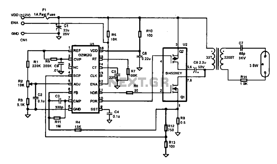
This document describes an efficient inverter control circuit designed for use as an LCD backlight power supply. The circuit is primarily managed by the chip UL (02962G), which interfaces with a driving field-effect transistor (U2), a voltage transformer, the...