
Temperature measurement using two cables
The sensor operates on alternating voltage, while the output temperature signal remains constant. The sensor is powered by a sine wave oscillator constructed using operational amplifiers A1 and A2. The AC supply is delivered through a two-conductor cable via coupling capacitor C6. The resulting waveform is then rectified, doubled, and smoothed using diodes D1, L2, and capacitors C1 and C2. Resistor R2 serves to isolate the output from the load, while ballast I1 facilitates the coupling of the sensor's output signal to the cable. This arrangement, along with capacitor C2, protects the sensor output from the alternating voltage present on the cable. At the other end of the cable, a network comprising resistor R3, inductor L2, and capacitor C4 forms a low-pass filter that mitigates the risk of the alternating voltage interfering with the sensor's output signal. Capacitor C3 acts as a barrier to prevent voltage leakage through resistor R3 to ground. If leakage occurs, the voltage reaching the measuring circuit or display will be diminished, resulting in inaccurate temperature readings. The input impedance of the device that measures the thermally dependent voltage should be at least 100 kΩ. The circuit requires a power supply of a few milliamperes to function properly.
The design of this circuit emphasizes the importance of maintaining signal integrity over long distances, particularly in applications where temperature monitoring is critical. By utilizing a combination of filtering and isolation techniques, the circuit effectively minimizes the impact of external noise and ensures accurate temperature readings. Additionally, the choice of sensors and the configuration of the power supply are crucial factors that contribute to the overall performance and reliability of the temperature measurement system.In those cases we want to measure the temperature in an area far from where it is. The imaging unit installed, you should find some way to connect the latter with the necessary sensor. The cables we use most often will have three two conductors for power sensor and one more to carry the signal representing the temperature.
But it may have only two, assuming that one will carry the potential of land and the second supply voltage with the signal temperature. This is possible if used as sensors or the LM334 or the LM335. The disadvantage arises but with them is that the temperature display is provided for reference the absolute zero (Kelvin scale), which most often is not as convenient as we would like.
If so the issue is a signal proportional to the temperature scale Celsius which in everyday life, you should use a different sensor, such as the LM45. The sensor is powered alternating voltage, while the signal at the exit temperature is constant. The power sensor is provided by a sine oscillator based on Operational A 1 and A2 (see figure). H, AC supply must him through a two-conductor cable through the coupling capacitor C6. Then the trend was rectified, doubled and smoothed by diodes D 1, L2 and capacitors C1, C2. The resistor R2 isolates the output on the tonnage of cargo and the ballast I1 makes the coupling of the output signal sensor cable. The same device, in combination with C2, protects the sensor output the alternating voltage that exists on the cable.
At the other end of the cable netting R3-L2-C4 forming a low pass filter that prevents the alternating voltage overlap continuously enhanced by the output of the sensor. The capacitor C3 is a barrier that prevents the leakage of voltage through R3 to earth. If this happens, the voltage reaches the measuring circuit / display will be reduced, giving incorrect temperatures.
The input impedance of the device that measures the thermally dependent voltage should be at least 100 KO. The circuit requires to operate the power of some mA. 🔗 External reference
Related Circuits

GTP USB PIC Programmer (Open Source). This project includes the GTP USB (not plus or lite). The schematic, photos, and PCB have been developed by PICMASTERS. The GTP USB PIC Programmer is an open-source device designed for programming PIC microcontrollers...

A temperature sensor can be created using a standard silicon diode, which produces approximately 2.2 mV per degree Celsius variation. An operational amplifier (OP amplifier) is utilized with a positive reference temperature (room temperature). The output signal is amplified...

This circuit is a slight modification of a previous design. In the earlier version, the switch needed to be held down for the entire duration of the music playback. In this updated circuit, pressing the push button once charges...
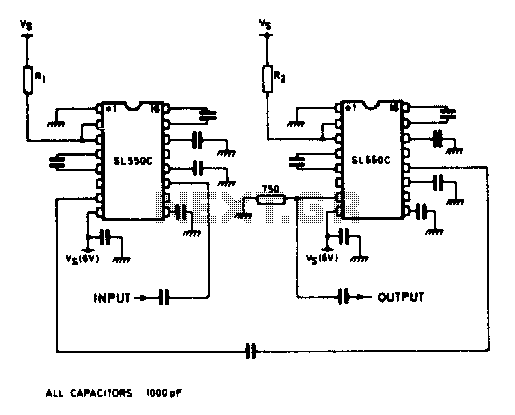
A wideband high gain configuration using two SL550s connected in series. The first stage is connected in a common emitter configuration, while the second stage is a common base circuit. Stable gains of up to 65 dB can be...
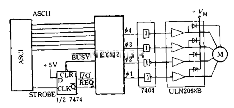
The CY512 is an easily developed system that operates using ASCII keyboard code. It features three operating modes: 1) Immediate command execution mode, where users can input ASCII commands to directly control the stepping motor movement in decimal stepping...
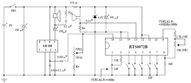
This voice changer circuit diagram is an electronic project developed using the RTS0072B single-chip CMOS LSI, specifically designed for voice-changing applications. It can transpose or distort one voice into another by encoding the input audio signals at normal speed...