
Two-stage wideband amplifier
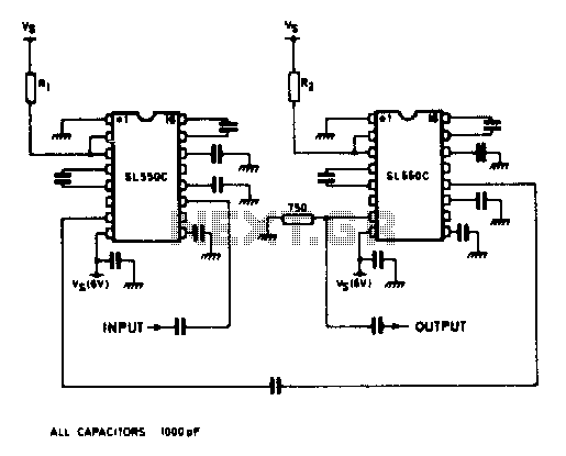
The described circuit utilizes two SL550 transistors to create a high-gain amplifier configuration. The first stage, configured as a common emitter amplifier, provides voltage amplification and is characterized by its high input impedance and low output impedance. This configuration is effective for providing significant gain, which is essential for applications requiring amplification of weak signals.
The second stage operates in a common base configuration, which is advantageous for its low input impedance and high output impedance characteristics. This stage is particularly effective in enhancing bandwidth while maintaining stability and linearity. The combination of these two configurations allows for a broad operational bandwidth from 5 MHz to 130 MHz, making it suitable for various RF applications.
The selection of resistors Rl (load resistor) and R2 (emitter resistor) is critical in achieving the desired gain of up to 65 dB. Proper values for these resistors will ensure optimal performance of the amplifier, balancing gain with stability and minimizing distortion. The low noise figure, marginally exceeding 2 dB, indicates that this configuration is capable of maintaining a high signal-to-noise ratio, which is crucial in communication systems where signal integrity is paramount.
Overall, this wideband amplifier configuration is well-suited for applications in telecommunications, signal processing, and other areas where high gain and bandwidth are essential. Its design effectively leverages the characteristics of both common emitter and common base stages to deliver reliable performance in demanding environments.A wideband high gain configuration using two SL550s connected in series. The first stage is connected in common emitter configuration, the second stage is a common base circuit. Stable gains of up to 65 dB can be achieved by the proper choice of Rl and R2 The bandwidth is 5 to 130 MHz, with a noise figure only marginally greater than the 2 dB specified for a single stage circuit. 🔗 External reference
Related Circuits
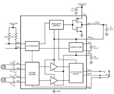
The LM48824's Stereo Headphone Amplifier, utilizing Class G architecture, enhances audio playback time for devices such as MP3 players and mobile TVs. Its adaptive power supply design allows for very low supply rails, effectively doubling power efficiency in comparison...
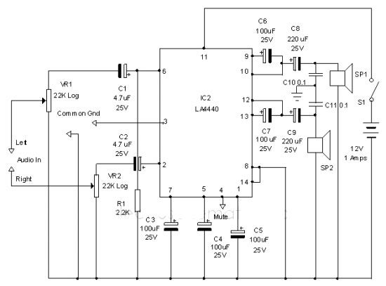
The LA4440 audio amplifier IC can be utilized to design a straightforward stereo power audio amplifier project, capable of delivering 6 watts of output power into an 8-ohm load. This audio amplifier IC features a minimal number of external...
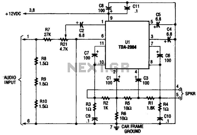
Only one channel of this circuit is shown. The other is practically identical. The input to the circuit, taken from the speaker output of a car radio, is divided into two paths. In one path, a high-power divider network...
The circuit was designed to create a modular Class A buffer preamplifier to isolate stages in an audio circuit. BF245 is a general-purpose N-Channel JFET used in this design. The modular Class A buffer preamplifier serves as an essential component...
The total gain of the car antenna amplifier is approximately 30 dB, with an input impedance of around 10 kΩ at 30 MHz. The amplifier should be mounted directly at the base of the antenna to prevent signal losses...
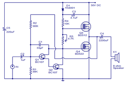
This is a 10W MOSFET audio amplifier circuit that operates from a single power source. Single rail configurations are seldom used in Class B power amplifiers; however, they are suitable for low-power applications like this one. This circuit design...