
Temperature Probe for Digital Multi Meter
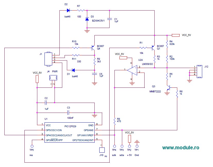
The temperature measurement probe circuit is designed to accurately monitor temperature variations in various environments, including printed circuit boards (PCBs) and at the probe tip itself. The circuit typically incorporates a temperature sensor, such as a thermistor or an integrated circuit (IC) temperature sensor, which converts temperature changes into an electrical signal.
In a standard configuration, the temperature sensor is connected to an analog-to-digital converter (ADC) that digitizes the analog signal for further processing. The ADC output can be interfaced with a microcontroller or a digital display unit to provide real-time temperature readings. The choice of sensor will depend on the required temperature range, sensitivity, and response time.
Additional components may include resistors for setting reference voltages, capacitors for filtering noise, and operational amplifiers to enhance the signal strength. The circuit may also feature a power supply section, which could be a battery or an external power source, ensuring stable operation.
For applications requiring data logging or remote monitoring, the circuit can be expanded with communication interfaces such as I2C, SPI, or UART, enabling connectivity with other devices or networks. The layout of the PCB should minimize thermal interference and ensure proper placement of the probe for accurate readings.
Overall, this temperature measurement probe circuit serves as a fundamental building block for various applications in environmental monitoring, industrial automation, and consumer electronics.This is a simple temperature measurement probe circuit. This circuit measures temperature either on a PC board or at the probe tip to which contains the.. 🔗 External reference
Related Circuits
This project provides a simple temperature-controlled fan. If the difference between the actual temperature and the user-defined temperature is significant, the fan will operate. The temperature-controlled fan circuit utilizes a temperature sensor, a microcontroller, and a fan motor to regulate...
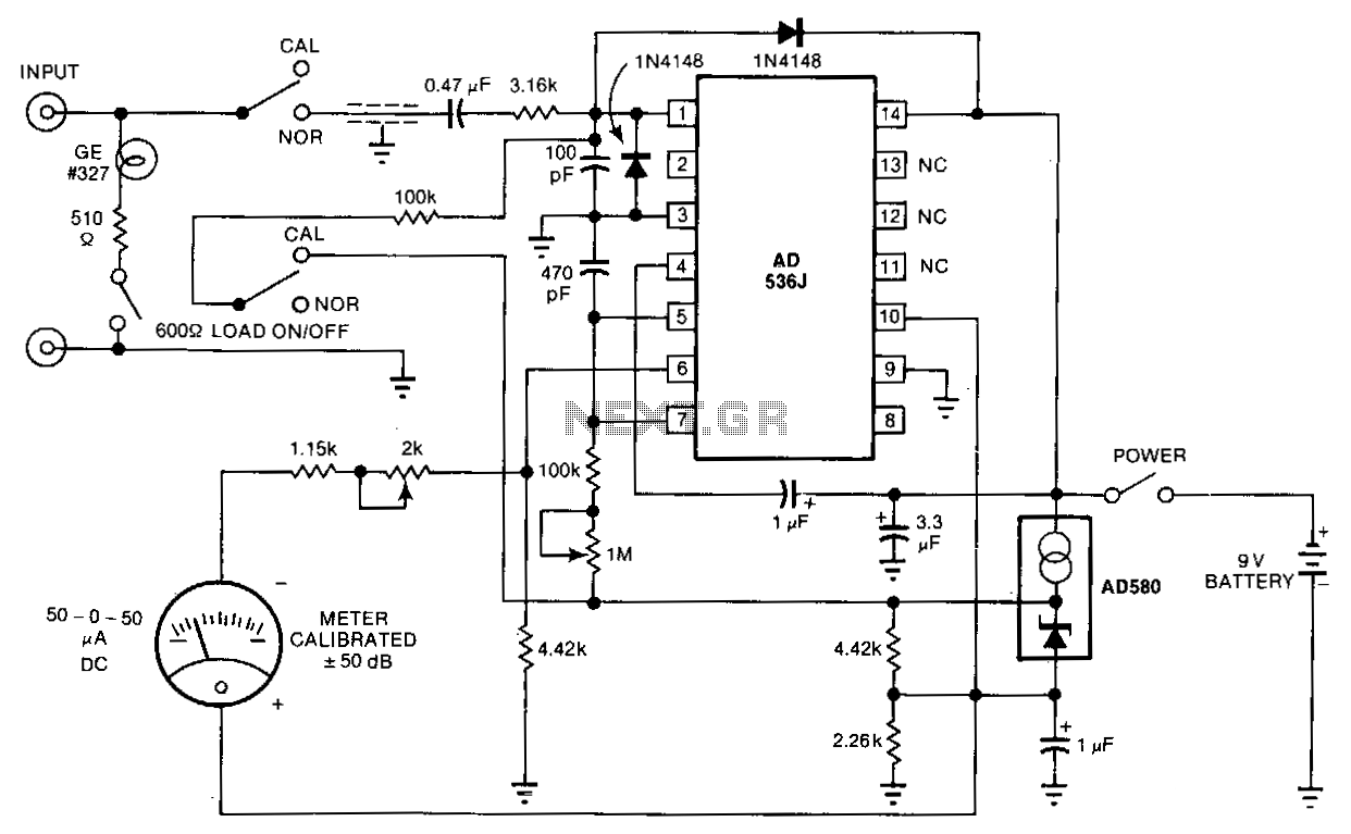
The telephone-line decibel meter and line-voltage sensor enables accurate monitoring and adjustment of telephone sound levels. The 600-ohm resistor appropriately terminates the line. The power consumption from the 9-volt battery is 2 mA, and the meter offers a ±30...
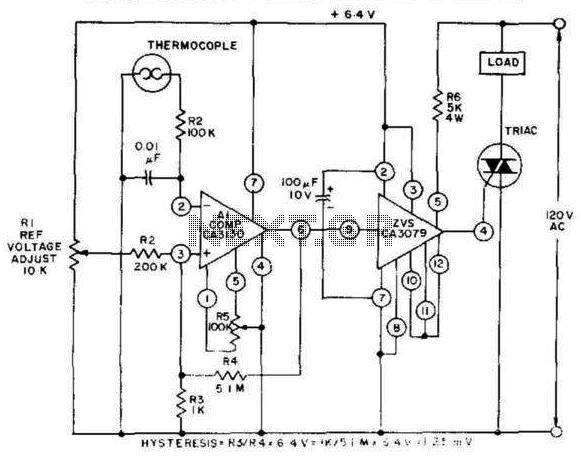
This control, featuring zero-voltage load switching, utilizes a CA3130 BiMOS operational amplifier and a CA3079 zero-voltage switch. The CA3130, functioning as a comparator, is particularly suited for comparing the low voltages produced by a thermocouple against an adjustable reference...
Unlike most surface-mounted device (SMD) resistors, SMD ceramic capacitors do not have their values marked. To determine the value of these capacitors, a capacitance meter is required. SMD ceramic capacitors are widely used in modern electronic circuits due to their...
The circuit is a preamplifier with digital regulation intensity of sound. It is separated into three departments. The first schematic (Fig.1) shows the control circuit of the electronic potentiometer. The control is achieved through two pressing switches. The S1...
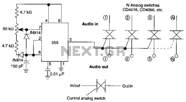
A 555 timer can be configured to simulate a multi-gang potentiometer by controlling the mark-space ratio. The switching rate should be at least twice the maximum expected signal frequency that the potentiometer has to handle. The 555 timer is an...