
Temperature Sensor with Digital Output

The circuit utilizes the LM35DT temperature sensor, which is designed to provide a linear output voltage that corresponds to the temperature in degrees Celsius. The LM35DT operates with a supply voltage of +5V DC and outputs 10mV for each degree Celsius increase in temperature, resulting in a sensitivity of 2mV/°C. This output is fed into the ADC0804, a popular 8-bit analog-to-digital converter capable of converting the analog voltage to a digital representation.
The ADC0804 features a simple interface, with the analog input connected to one of its input pins. The conversion process is initiated by applying a logic high to the start conversion pin, which allows the ADC to process the input voltage. The digital output from the ADC0804 is an 8-bit binary number that represents the temperature in digital form.
The digital output can be used to control an LED indicator. In this configuration, the LED is turned ON when the output logic is 0 and turned OFF when the output logic is 1, providing a simple visual representation of the temperature status. Furthermore, the digital output can be connected to a 7-segment display driver, allowing for a more user-friendly temperature readout. A common 7-segment display driver can be used to convert the 8-bit binary output into a format suitable for driving a 7-segment display, providing a clear numerical representation of the temperature being sensed.
Overall, this circuit provides a straightforward and effective method for temperature measurement and display, utilizing widely available components and simple interfacing techniques.This is a very simple to implement Temperature Sensor. It uses LM35DT as a semiconductor temperature sensor which operates with a +5 volt DC. It produces an analog output voltage, proportional to the change in surrounding temperature in Celsius scale (2mv/C). The analog output of the sensor is then passed to the ADC0804 IC which produces an 8-bit binary output (digital output) correspoding to the analog input voltage.
The digital output from ADC is then used to glow the LED which indicates the high/low logic (LED ON: Logic 0, LED OFF: Logic 1). The output of the ADC can be interfaced to a 7-segment diaply using a 7-segment driver or the digital output can be interfa
🔗 External reference
Related Circuits

This circuit is used for a Digital Radar Speedometer. It allows for the measurement of the speed of any moving object, particularly vehicles such as cars. The speed is displayed in kilometers per hour (KPH) with a three-digit display....
This tester is designed to locate stray electromagnetic (EM) fields. It can easily detect both audio and RF signals up to frequencies of approximately 100 kHz. However, it should be noted that this circuit is not a metal detector,...
The driver stage operates similarly to the previously described class A output stage, but it functions at a few milliamps, making efficiency less of a concern. The biasing configuration should be recognizable. Some circuits, including the one mentioned, incorporate...
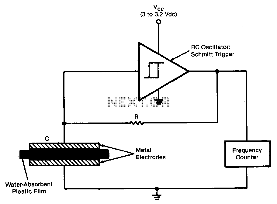
The sensor operates as an RC oscillator, utilizing a water-absorbent plastic film as the insulator within the capacitive element. The capacitance of this film increases with the amount of water it absorbs from the air, resulting in a reduction...
This is a simple mains power failure alarm circuit that activates an alarm when the mains supply is lost. Unlike many similar circuits, this design does not require a backup power source, such as a battery, to operate the...
This circuit controls a load, specifically a DC brushless fan, based on a temperature comparison with a setpoint. The transducer utilized is a diode in the forward bias configuration. When forward biased, the forward voltage drop across the diode...