
Electromagnetic Field Probe with Meter Output
This electromagnetic field tester circuit utilizes an operational amplifier (op-amp) configured to amplify the AC signal generated by electromagnetic fields. The design includes a frequency response range optimized for detecting signals between 50 Hz and 100 kHz, making it suitable for both audio and radio frequency applications. The op-amp's gain is influenced by a 150 pF capacitor, which helps shape the frequency response and limits gain at higher frequencies.
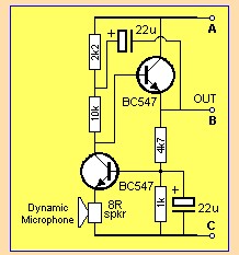
The probe consists of a radial inductor connected to a 50 cm screened cable, which enhances the detection capability while minimizing interference from external sources. The output from the op-amp is an AC voltage proportional to the strength of the detected electromagnetic field. This signal undergoes further amplification through a BC109C transistor, which is configured to provide additional gain necessary for effective rectification and measurement.
Rectification is performed using a full-wave rectifier configuration, which typically includes diodes that convert the AC signal to a DC voltage suitable for driving a small panel meter with a full-scale deflection of 250 µA. The rectified signal is then filtered by a capacitor to smooth out fluctuations, providing a stable reading on the meter.
The circuit allows for audio monitoring through stereo headphones connected to socket SK1, enabling real-time audio feedback of the detected frequencies. This feature is particularly useful for identifying the presence of electromagnetic interference from various electrical devices.
For practical testing, an audio signal generator can be employed to create a controlled electromagnetic field, which can be detected by the probe, allowing for verification of the circuit's functionality. Alternatively, the probe can be used in proximity to live electrical systems, where it will indicate the presence of stray electromagnetic fields generated by AC currents in wiring and devices.
Overall, this tester is a versatile tool for detecting electromagnetic fields, providing valuable insights into the presence of stray signals and potential interference in electronic systems.This tester is designed to locate stray electromagnetic (EM) fields. It will easily detect both audio and RF signals up to frequencies of around 100kHz. Note, however that this circuit is NOT a metal detector, but will detect metal wiring if it conducting ac current. Frequency response is from 50Hz to about 100kHz gain being rolled off by the 150p capacitor, the gain of the op-amp and input capacitance of the probe cable. Stereo headphones may be used to monitor audio frequencies at the socket, SK1. I used a radial type inductor with 50cm of screened cable threaded through a pen tube. The cable may be used with a plug and socket if desired. My probe is shown below: The output signal from the op-amp is an ac voltage at the frequency of the electro-magnetic field. This voltage is further amplified by the BC109C transistor, before being full wave rectified and fed to the meter circuit.
The meter is a small dc panel meter with a FSD of 250uA. Rectification takes place via the diodes, meter and capacitor. If you have access to an audio signal generator you can apply an audio signal to the windings of a small transformer. This will set up an electromagnetic field which will be easily detected by the probe. Without a signal generator, just place the probe near a power supply, mains wiring or other electrical device.
There will be a deflection on the meter and sound in the headphones if the frequency is below 15KHz. Switch on, plug in headphones (optional) and move the probe around. Any electrical equipment should produce a hum and indicate on the meter. I remember once building a high gain preamp (for audio use). I made a power supply in the same enclosure. The preamp worked, but suffered from an awful mains hum. This was not directly from ripple on the power supply as it was regulated and well smoothed. What I had done was built the audio circuit on a small piece of veroboard, and placed it within a distance that was less than the diameter of the transformer. The transformers own electromagnetic field was responsible for the induced noise and hum. I should however note, that this was when I was new to electronics with very little practical experience.
You can now buy toroidal transformers which have a much reduced hum field. 🔗 External reference
Related Circuits
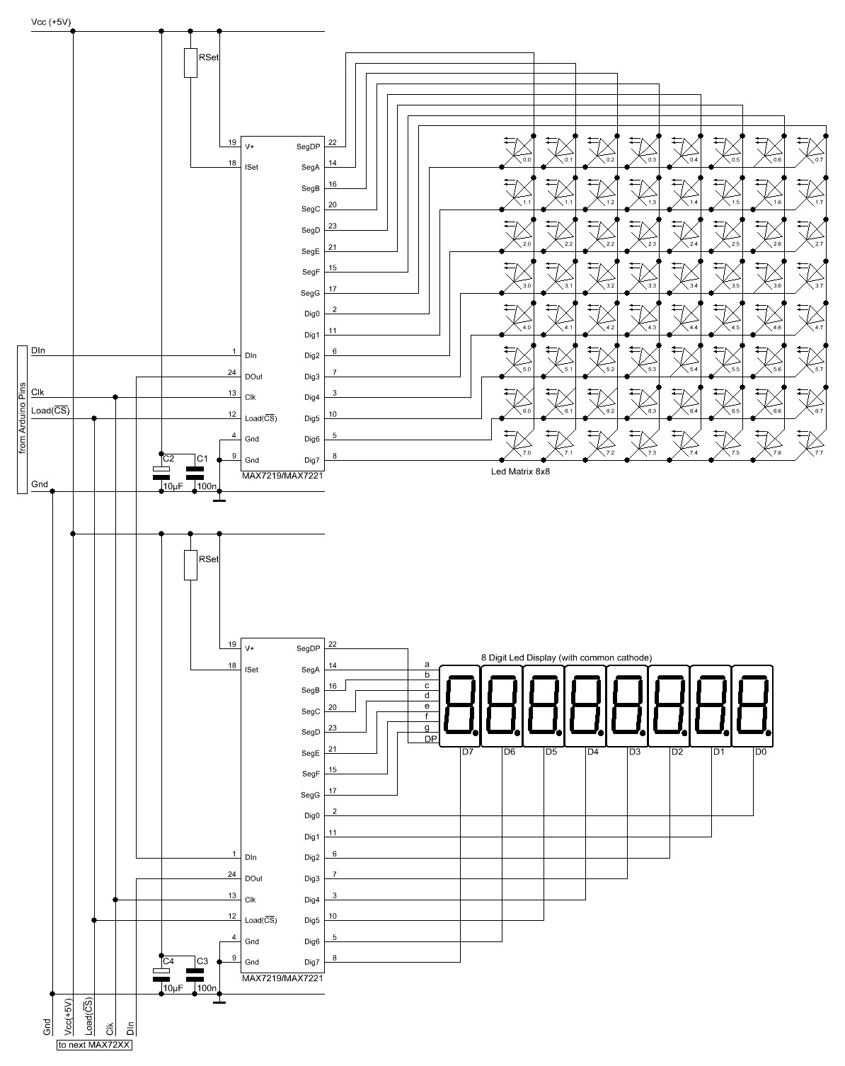
The Arduino website provides comprehensive documentation on connecting LEDs to the Arduino using the MAX7221. A specific set of components is required for this setup. The MAX7221 is a versatile LED driver that enables the control of multiple LEDs through...
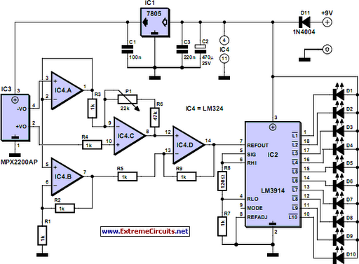
This is a stereo LED level meter. It is the most affordable and effective bar graph display available, utilizing commonly accessible components. The circuit requires only a few LEDs, 22 transistors, some resistors, diodes, and a set of electrolytic...
While it may lack the aesthetic appeal of traditional mercury barometers featuring elongated glass tubes mounted on intricately carved wood, the Torricelli barometer presented here serves as a functional equivalent and an electronic representation of the original Torricelli barometer....
The Kill A Watt is a product that measures volts, amps, and power factor of individual appliances, allowing users to calculate power consumption and running costs. However, a desire for a solution that provides similar data for an entire...
This circuit generates a readout for a digital tachometer. IC9 functions as a 3-digit LED display driver, counter, and latch. IC8 operates the common cathode LEDs, which are activated by transistors Q1, Q2, and Q3. Refer to page 268,...
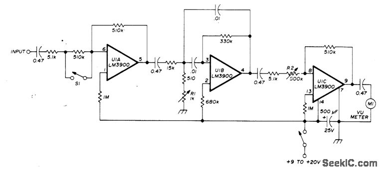
A simple and easily transportable VSWR meter is composed of a high-gain amplifier, a narrow-bandwidth selective amplifier tuned to 1000 Hz with a bandwidth of 100 Hz, and a variable-gain output amplifier that drives a low-cost VU meter. This...