
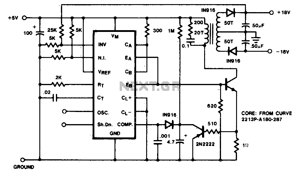
Temperature-to-frequency converter
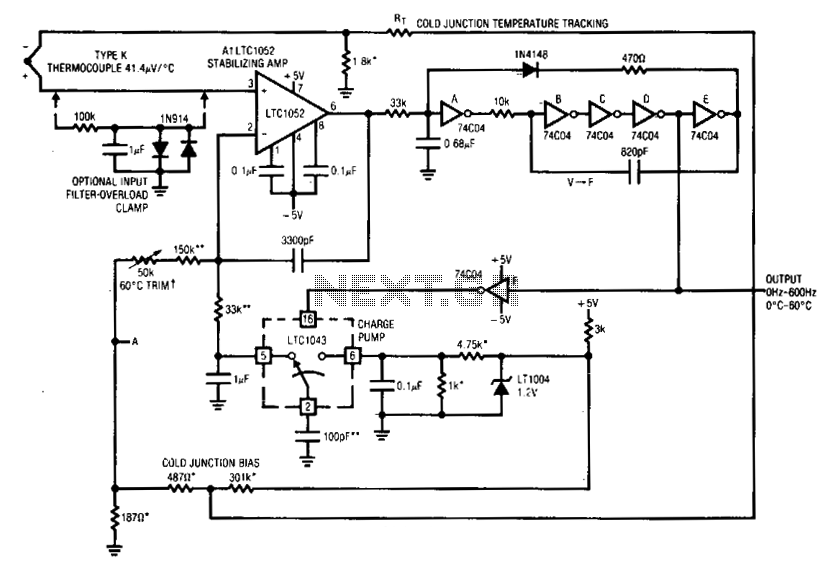
In this electronic circuit, Al's positive input, influenced by the thermocouple, serves as a critical reference point for the operation of the voltage-to-frequency (V-F) converter. The 74C04 inverters function as the core of the converter, transforming the analog voltage signal into a frequency output. The design incorporates a feedback loop that ensures the stability and accuracy of the system.
The 100 pF capacitor acts as a charge reservoir, releasing a fixed charge to the 1 µF capacitor during each pulse generated by the V-F converter. The LT1043 switch plays a vital role in controlling the transfer of charge between these capacitors, ensuring that the integration process occurs smoothly. The integration of charge in the larger capacitor results in a DC voltage that is fed back to the negative input of Al, creating a balance between the amplifier's inputs.
The feedback mechanism is crucial in eliminating drift and reducing nonlinearities, which can introduce errors in the output frequency. The output frequency is thus a direct reflection of the steady-state DC conditions at Al's inputs, emphasizing the importance of precise input biasing.
To enhance the stability of the circuit, a 3300 pF capacitor is employed, which establishes a dominant response pole at Al. This component is essential for controlling the frequency response of the feedback loop, ensuring that the system remains stable under varying conditions. The careful selection of these components and their arrangement within the circuit contributes to the reliable performance of the V-F converter, making it suitable for applications requiring accurate frequency generation from voltage signals.Al's positive input is biased by the thermocouple. Al's output drives a crude V — F converter, comprised of the 74C04 inverters and associated components. Each V — F output pulse causes a fixed quantity of charge to be dispensed into the 1 µ¥ capacitor from the 100 pF capacitor via the LT1043 switch.
The larger capacitor integrates the packets of charge, producing a dc voltage at Al's negative input. Al's output forces the V-* F converter to run at whatever frequency is required to balance the amplifier's inputs.
This feedback action eliminates drift and nonlinearities in the V — F converter as an error item and the output frequency is solely a function of the dc conditions at Al's inputs. The 3300 pF capacitor forms a dominant response pole at Al, stabilizing the loop. 🔗 External reference
Related Circuits
The VFC62 is a voltage-to-frequency and frequency-to-voltage converter that effectively transforms analog signals into digital signals. The digital output is presented in an open collector format, where the digital pulse repetition rate is directly proportional to the amplitude of...
This circuit converts frequency to voltage by taking the average DC value of the pulses from the 74121 monostable multivibrator. The one-shot is triggered by the positive-going AC signal at the input of the 529 comparator. The amplifier acts...
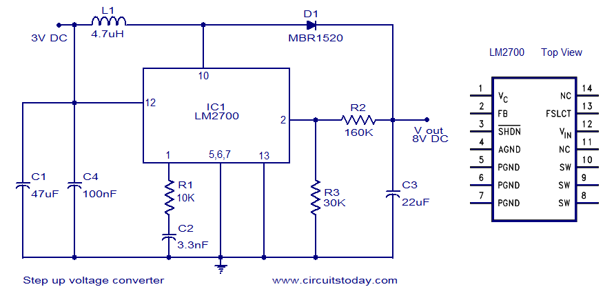
A simple DC to DC step-up voltage converter circuit schematic using the LM2700, which is a step-up switching converter. The LM2700 is a versatile step-up switching converter designed to efficiently convert a lower input voltage to a higher output voltage....

This design circuit serves as a converter utilizing the LM2623A ratio adaptive circuit to drive a digital camera motor. It generates 5 volts from input voltages that range between 1.8 and 4.5 volts. The circuit's duty cycle, while not...
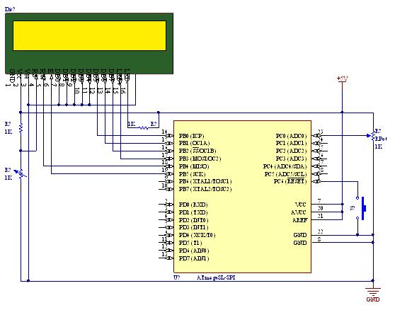
A straightforward tutorial on utilizing the ADC (Analog to Digital Converter) unit of the AVR microcontroller, demonstrated with the Atmega8, including a circuit diagram and code examples. The ADC unit in the Atmega8 microcontroller is a crucial component that allows...
A low-current flyback converter is utilized to generate ±15 volts at 20 mA from a +5 volt regulated line. The reference generator in the SG1524 is not used, with the input voltage serving as the reference. Current limiting in...