
Step up Voltage converter DC to DC
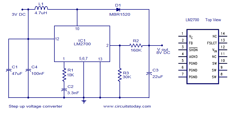
The LM2700 is a versatile step-up switching converter designed to efficiently convert a lower input voltage to a higher output voltage. This circuit is particularly useful in applications where the supply voltage is insufficient for the required load, such as powering portable devices from a single-cell battery.
The schematic typically includes several key components: the LM2700 integrated circuit, input and output capacitors, an inductor, a diode, and feedback resistors. The input voltage is applied to the LM2700, which controls the switching of the internal transistor. The inductor stores energy during the 'on' phase and releases it to the output during the 'off' phase, effectively increasing the voltage.
The output voltage can be adjusted by selecting appropriate values for the feedback resistors, allowing for a range of output voltages to be achieved based on the application requirements. The output capacitor smooths the output voltage, providing a stable power supply to the load.
The circuit should also include necessary protection features, such as input and output capacitors to filter noise, and possibly a thermal shutdown feature to protect against overheating. Proper layout and component selection are critical to minimize losses and ensure stable operation across varying load conditions.
In summary, the LM2700-based step-up converter circuit is an efficient solution for applications requiring a higher voltage from a lower input, with flexibility in output voltage settings and essential protective components for reliable performance.A simple dc to dc step up voltage converter circuit schematic using LM2700-which is a step up switching converter.. 🔗 External reference
Related Circuits
All miniature electronic devices operate off batteries. Some of them require higher than the standard battery voltages for efficient operation. If a battery with the specific voltage is unavailable, additional cells must be connected in series to increase the...
The voltage to frequency converter (V/FC - VCO) circuit consists of a UJT (uni-junction transistor) oscillator in which the timing charge capacitor C2 is utilized. The voltage to frequency converter circuit operates by converting an input voltage into an output...
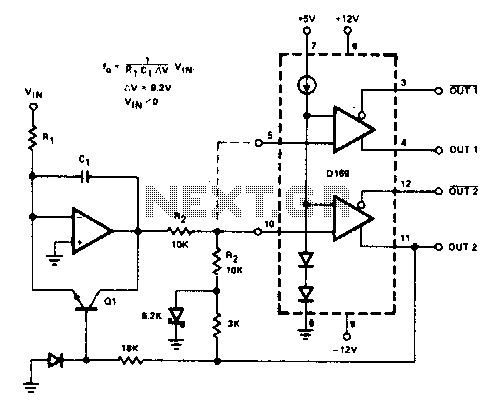
The D169 functions as a level detector, offering complementary outputs. An operational amplifier (op amp) is employed to integrate the input signal Vin, utilizing a time constant defined by the resistor R1 and capacitor C1. A negative input signal...
A DC/DC converter IC from Linear Technology, the LT1615 step-up switching voltage regulator, is capable of generating an output voltage of up to +34V from a supply voltage ranging from +1.2V to +15V, utilizing only a few external components....
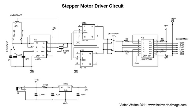
The commonly used 555 timer is configured for a variable mark/space ratio, which is essential for this application. Additionally, two D-type flip-flops (4013) are employed to provide the necessary count for the ULN2003 stepper motor driver. ULN2003 components may...
Stepper motors are a frequently discussed topic. This circuit converts a clock signal from a square wave generator into signals that have a 90-degree phase difference, which are necessary for driving the stepper motor windings. The trade-off for this...
Warning: include(partials/cookie-banner.php): Failed to open stream: Permission denied in /var/www/html/nextgr/view-circuit.php on line 713
Warning: include(): Failed opening 'partials/cookie-banner.php' for inclusion (include_path='.:/usr/share/php') in /var/www/html/nextgr/view-circuit.php on line 713