
Darkroom time exposure of the second circuit
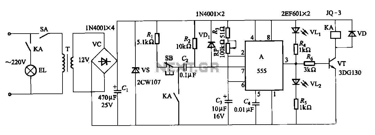
The described circuit employs a 555 timer IC configured in monostable mode to create a time delay for exposure in a darkroom setting. The 555 timer generates a pulse output upon receiving a trigger signal, which initiates the timing cycle. The relay, activated by the output of the 555 timer, controls the power to the exposure light source, ensuring that the light is turned on for the duration specified by the timing circuit.
Potentiometer RP serves as the primary means for adjusting the exposure time. Its resistance value directly affects the time constant of the timing circuit, which is determined by the formula T = 1.1 * R * C, where T is the time in seconds, R is the resistance in ohms, and C is the capacitance in farads. By varying the resistance of RP, the exposure time can be finely tuned between 1 second and 120 seconds.
For applications requiring longer exposure times beyond the standard range, the circuit can be modified by increasing the capacitance of capacitor C4. This adjustment increases the time constant of the circuit, thereby extending the maximum exposure time. It is essential to ensure that the relay used can handle the power requirements of the exposure light source and that the components are rated appropriately for the voltages and currents involved in the circuit.
Overall, this darkroom exposure control circuit provides a flexible and efficient solution for managing light exposure times, suitable for various photographic processes. Proper calibration of the potentiometer and capacitor will ensure optimal performance and reliability during operation.Darkroom time exposure of the second circuit It uses 555 IC A for the timing circuits. KA by the relay contacts to the control system of the exposure light source. Adjustment p otentiometer RP, exposure time can be varied within the scope of 1-120s. For more long delay, may increase the capacity of the capacitor C4.
Related Circuits
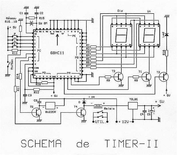
The timer is proposed an effective model for controlling an external load 8A/380V. Equipped with a 68HC11 mu.P associated with an 8 MHz crystal, it can get very precise programmable durations. Two lines are planned: from 0 to 99...

The preamplifier circuit is designed to offer appropriate loading for phono cartridges with reluctance. It achieves a gain of approximately 25 dB at 1 kHz (converting an input of 2.2 mV to an output of 100 mV). The circuit...
The FM modulator circuit, which utilizes frequency modulation, is constructed using a Motorola MC1648P oscillator. Two varactors, specifically Motorola MV-209, are employed to modulate the frequency of the oscillator. A 5000-ohm potentiometer is incorporated to bias the varactors for...
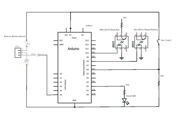
Water drops have always captivated those interested in time-lapse and macro photography, serving as a common entry point into this fascinating field. However, further research reveals that photographing these tiny splashes involves more complexity than initially apparent, as the...
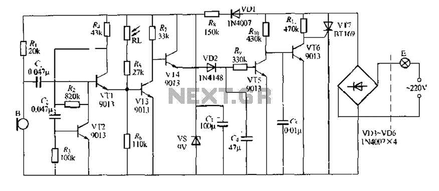
This circuit design is a sound and light control delay switch for staircase walkway lighting, featuring high voice sensitivity. In the evening, when someone walks on the stairs, their footsteps activate the electronic meter, turning on the lights. If...
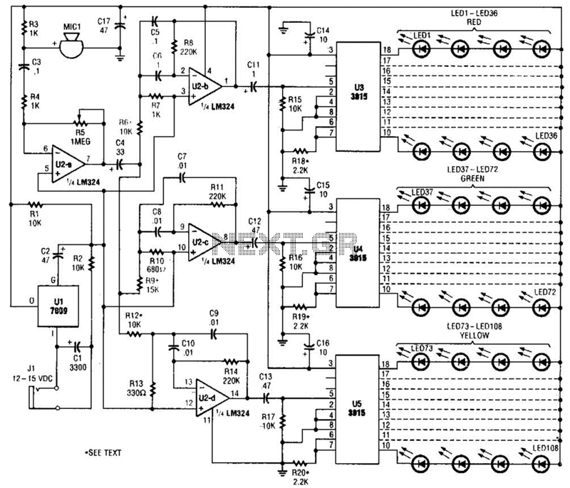
The microphone input, MIC1, is connected through capacitor C3 and resistor R4 to the inverting amplifier U2-a, where the gain of U2-a is adjusted by potentiometer R5. The output from U2-a is passed through capacitor C4 to the remaining...