
15db uhf tv antenna booster

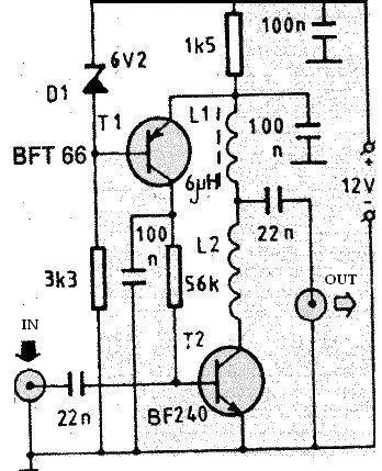
This UHF band preamplifier circuit is designed to enhance the reception of television signals in the UHF frequency range. The choice of the BF180 transistor is crucial, as it provides the necessary amplification characteristics suitable for UHF applications. The circuit employs a band-pass filter at the input stage, which is essential for selecting the desired frequency range while attenuating unwanted signals. The components C1, CV1, L1, L4, C7, and C3 work in conjunction to create a filter that allows only the UHF signals to pass through efficiently.
The output stage utilizes a common-base configuration, which is advantageous due to its low input impedance. This characteristic allows for better matching with the antenna, ensuring maximum power transfer. The inductors L1 through L4 are strategically placed to optimize the circuit's Q-factor, which is a measure of the selectivity and quality of the filter. A higher Q-factor results in a sharper frequency response, enhancing the circuit's ability to isolate the desired UHF signals from interference.
After the assembly of the circuit, it is essential to house it in a robust metal enclosure. This enclosure not only protects the components from physical damage but also serves to minimize electromagnetic interference (EMI) from external sources. Grounding the circuit to the metal box is critical, as it helps reduce noise and improves overall performance. Proper grounding practices ensure that any stray signals are diverted away from the sensitive components of the preamplifier, thereby enhancing the signal clarity and strength.
In conclusion, this UHF band preamplifier circuit is a well-designed solution for improving television signal reception. Its careful selection of components and configuration contributes to its effectiveness in amplifying UHF signals while minimizing noise and interference.This is an UHF bandage TV antenna preamplifier circuit With 15dB accretion to body easily. It is formed based on BF180 UHF Transistor. The aboriginal date is an bandage canyon clarify complete by the C1, CV1, L1, L4, C7 and C3, the additional date is a base-common voltage amplifier with low ascribe impedance to match. Body the L1 ~ L4 as air amoun t braid to access aerial Q-Factor. After assembling, backpack it into a able brownish box and affix the arena of the ambit to the box to abate babble effect. 🔗 External reference
Related Circuits
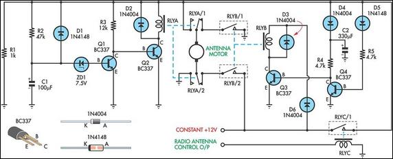
This up/down timer was designed to control a power antenna on a late-model vehicle. Normally, this vehicle uses a body computer to control the antenna. However, the owner intended to install a high-powered audio stereo system. The original stereo...
This 1 square meter antenna has radiation resistance of about 10 nanohoms, making the 0.4 Ohm resistance (including skin effect, which about doubled the resistance from the DC value) the dominant loss in the antenna. The lower the resistance,...

This circuit is designed for a UHF TV antenna and provides a 15 dB preamplification. It is constructed using a transistor and minimal components. The schematic features the BF180 UHF transistor. The first stage consists of a band-pass filter...
The PCB of this circuit should be positioned close to the antenna within a compact metallic enclosure. This VHF antenna circuit requires a 12 volts DC power supply, which can be sourced from a 12-volt battery, as the current...
This schematic represents a cable TV signal booster amplifier circuit designed to enhance the signal strength of a cable TV system. It is recommended to use 75 Ohm coaxial cables for both the input and output connections, and the...
This antenna tuning unit (ATU) allows half-wavelength or longer wire antennas to be matched to the 50-ohm antenna input of 27-MHz Citizens Band (CB) radios. The ATU is particularly useful in situations where a wire antenna is less visually...