
tesla tc plans
The method for calculating transformer input impedance involves using the values specified on the transformer. For example, if the transformer draws 2.2A at 220V, the impedance can be calculated as Z = 220V / 2.2A = 100 Ohm. Subsequently, the PFC can be calculated using the formula C = 1/(ωZ). At 50Hz, this would yield C = 1/(2π * 50 Hz * 100 Ohm) = 1/(π * 10) * 10^-3 F, which approximates to 31 µF. Consultation with neon sign manufacturers may provide access to PFC capacitors suitable for specific transformers.
It is important to note that the calculated 100% PFC may not yield the optimum value for spark-gap coils, as factors such as gap break rate can influence the power factor. For optimal performance, experimentation with different capacitance values or simulation calculations may be necessary.
Grounding considerations dictate that only components on the mains side that are accessible to the user—such as switches, dials, and variacs—should be grounded. The high-voltage (HV) secondary side of the transformer must remain ungrounded, even if it is a center-tapped NST. Connecting the RF ground to any part of the HV primary circuit is extremely dangerous, as this can lead to fatal electric shocks if contact is made with the secondary streamers. The energy from the primary circuit's capacitor could flow through the body to ground, where the low resistance of the human body offers little protection against high voltages. At 8kV, potentially lethal currents of around 10A could flow through the body, with even 5mA being sufficient to cause death.
Additionally, the mains ground wire is typically too thin to handle high-frequency signals effectively, resulting in significant impedance. A high-impedance ground can lead to improper grounding of the transformer circuit, causing voltage drops along the wire and potentially exposing parts of the system to high voltage. This could result in hazardous conditions, including corona discharge, electrocution, or equipment damage.
The issue of high impedance grounding also affects the zero voltage node, which can shift along the wire to where a solid ground exists, causing phase shifts in the transformer secondary. This may lead to unwanted electrical discharges from various points along the coil, rather than solely from the top. Furthermore, high-frequency currents tend to flow primarily along the surface of conductors, making the interior of a large conductor effectively non-conductive at very high frequencies. This phenomenon, known as skin effect, defines the skin depth as the depth at which current density falls to approximately 37% of its maximum value.A PFC capacitor on the mains side can act as "current limiting" to some extent. Otherwise, use resistive or additional inductive ballast (a MOT in series with shorted secondary winding). Power factor correction (PFC) shifts the VA rating of the transformer closer to actual input and/or output watts, and reduces input current needed.
Reduced current is a benefit as all your switches, relais`, fuse boxes and so on can be smaller - without PFC they would have to stand twice or more the current. Additionally, I2*R losses in the wire resistances would be at least four times as high. For example a 400VA cos(phi)=0. 55 transformer takes in about 0. 55*400VA ~= 200W with and without a PFC, but without a PFC it will draw about 2A from a 200VAC line. With an exactly matching PFC the input current is just ~ 1A. The capacitors are non polar capacitors, and it seems like they are mostly oil filled wax-paper capacitors used with mains voltage motors. Method: First calculate transformer input impedance according to the values written on the transformer.
For example 2. 2A @ 220V gives Z = 220V/2. 2A = 100 Ohm. Then calculate the PFC with C = 1/(wZ). At 50Hz, this would be 1/(2*pi* 50 Hz * 100 Ohm) = 1/(pi*10) * 10-3 F ~= 31 uF. You could also ask neon sign manufacturers if they have PFC caps for your particular transformer. Note: A fellow coiler pointed out that the above calculated 100% PFC may generally not give the optimum value for spark-gap coils, as the gap break rate and other things change the power factor. For a nice match it might be easier to try out different capacitances, or calculate by simulation. The only things that should/must be grounded to the mains grounding is the stuff on the mains side that you are going to touch (switches, dials, variac and so on).
The HV secondary side of the transformer must not be grounded at all, even if it is a center-tapped NST. Connecting together RF ground and any part of the HV primary, like done in some schematics, is absolutely lethal.
If you connected together the RF ground and some part of the HV primary circuit, you`re a definite goner (=dead) should you come into contact with the secondary streamers (which can be lethal in any case, see 6 Skin effect). The primary circuits capacitor energy would then flow partly (but partly is already enough) through your body towards the ground.
Your pitiful 500. 1000kOhm low-voltage body resistance is next to no obstacle for the high voltages - at 8kV, there could be potentially ~10 amps flowing through you, whereas even 5mA is enough to kill. also, the mains ground wire is way too thin, and would have a considerable impedance at the high frequencies present.
High impedance is not nice, as the TC base wouldn`t be properly grounded then, and the wire would have a voltage drop from some 10s of kV on the base to 0V somewhere along the wire - i. e. the thin wire could still have a few kV some meters away from the coil base (corona, electrocution, damaged equipment etc).
the other thing that is bad about a high impedance ground is that the zero voltage node will shift down along the wire to the place where the solid ground is. This will cause a phase shift also in the TC secondary, meaning you could get breakouts from any part along the coil, not just the top.
High frequency current tends to flow closer to the surface of conductors, i. e. at very high frequencies a huge round 1m2 area conductor will have current flow only on the surface - you could make the center hollow as the metal inside it conducts no current at all and only adds weight to the conductor. Skin depth = depth at which current density is 1/e ~= 37% of maximum. There IS current flow 🔗 External reference
Related Circuits
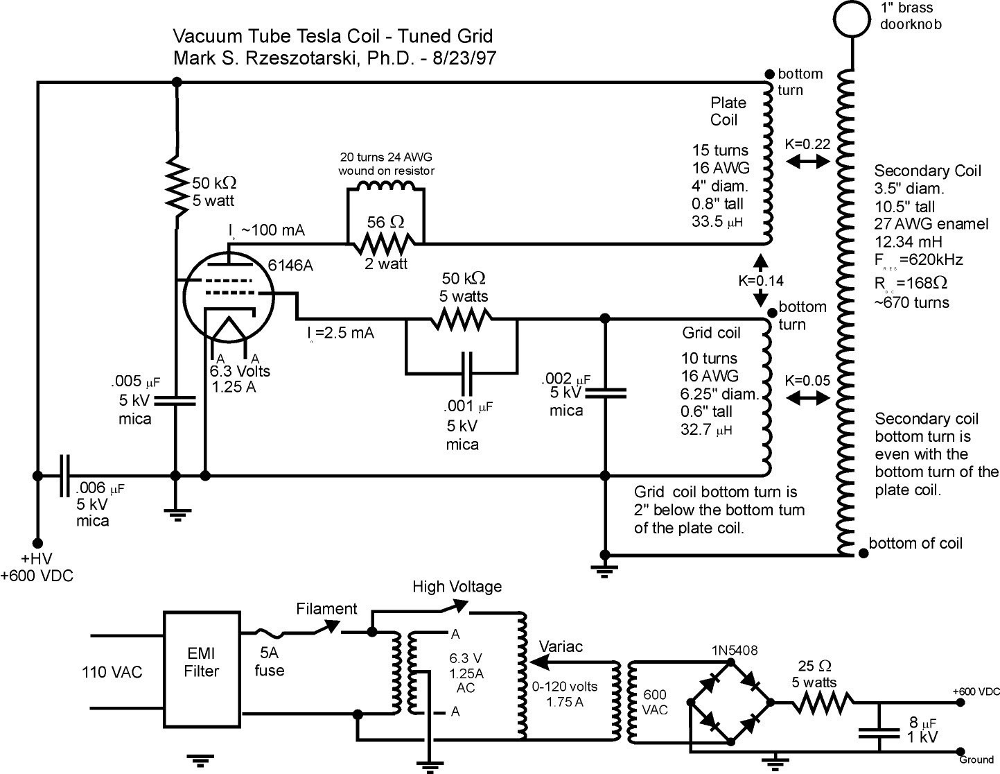
Vacuum tube Tesla coils operate in a continuous wave mode, providing constant energy to the Tesla coil secondary. Consequently, the output is mainly determined by the power capacity of the vacuum tube. The spark discharge and operation of these...
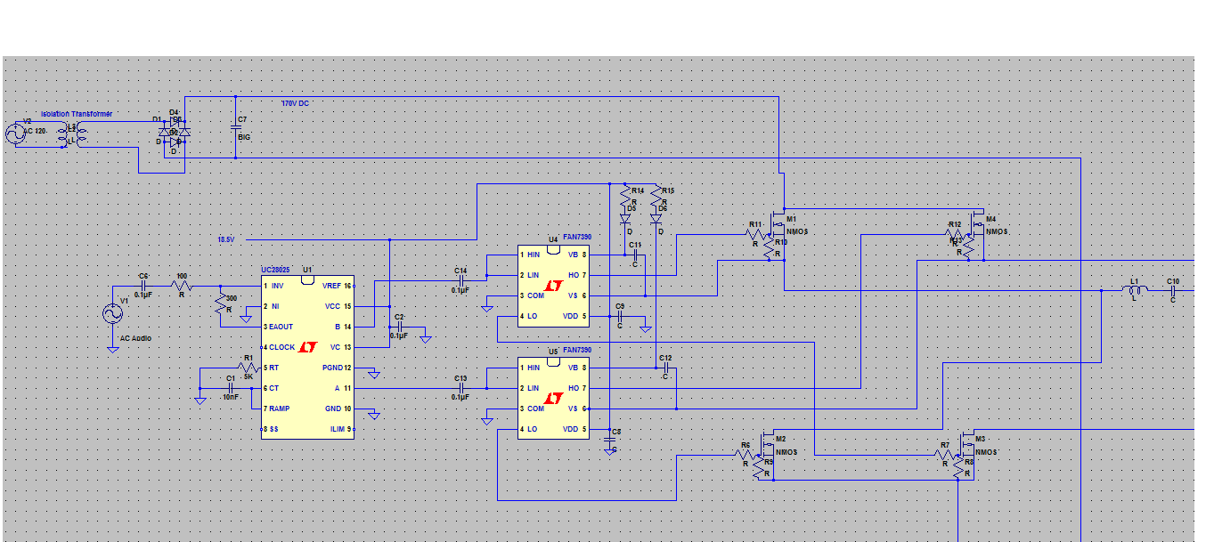
A Singing Tesla Coil is being developed for a 4-H electricity project, and the initial draft of the circuitry has been completed. The Singing Tesla Coil is an innovative device that produces high-voltage, high-frequency alternating current (AC) electricity, resulting in...
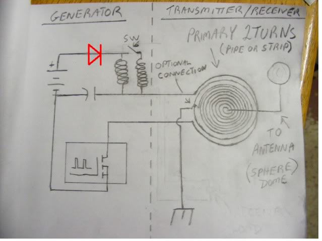
At approximately 50 kHz, a voltage exceeding 40 volts is observed at the receiver. LEDs illuminate without issues, although a 5mm LED was damaged. A capacitor connected to the AC was obstructing energy transfer. The primary negative was connected...
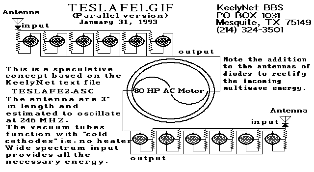
Two schematic diagrams illustrate a series and a parallel circuit configuration that Tesla may have utilized. The components featured are the 70L7GT Half Wave Rectifier tubes, which are surprisingly still available today. While there is an interest in accessing...
An SCR (Silicon Controlled Rectifier) functions similarly to a diode, allowing current to flow in one direction and can be turned on; it remains in this state until the power is interrupted. The query arises regarding its application in...

When operated through a spark gap, does a Tesla coil always operate at a quarter wave, half wave, or a multiple of a whole wave, resulting in 2*n maximums? Are there sources related to creating standing waves and the...