
the 555 precision timer ic
The 555 timer IC's versatility allows it to be configured for various applications, including astable, monostable, and bistable modes. In astable mode, the 555 timer continuously oscillates between high and low states, making it ideal for generating square waves. This configuration can be employed in applications such as LED flashers or tone generation. The frequency of oscillation is determined by the values of R1, R2, and C1, allowing for customization based on specific requirements.
In monostable mode, the 555 timer acts as a one-shot timer, producing a single pulse of a specified duration in response to a triggering event. This mode is useful for applications such as pulse-width modulation (PWM) or creating delays in circuits. The output pulse width can be adjusted by varying R1 and C1, providing flexibility in timing applications.
Bistable mode allows the 555 timer to function as a flip-flop, maintaining its output state until triggered again. This configuration is suitable for applications requiring stable on/off states, such as toggle switches or memory elements in digital circuits.
The simplicity of the 555 timer circuit design, combined with its low cost and broad functionality, contributes to its enduring popularity in electronic design. Its ability to operate across a wide voltage range and deliver reliable performance with minimal external components makes it a staple in both educational and professional electronic projects.Considering the pace of change in the electronics industry, the 555 could be the constant in an ever-changing universe. But what is the 555 How does it work How can we use it And why do we still use it In this introductory article we will try to answer these questions.
If you would like to see some examples, visit here. The 555 timer is the solution to a problem found by the inventor Hans Camenzind. He saw the need through his radio work for a part that could act as an oscillator or a timer [1]; and working as a contractor for Signeticsdeveloped the 555. (Signetics was purchased by Philips in 1975, and their semiconductor division was spun off as NXP in 2006).
The 555 has to be one of the most used ICs ever invented. It is used for timing, from microsecondsto hours; and creating oscillations (which is another form of timing for the pedants out there). It is very flexible with operation voltage, you can throw from 4. 5 to 18Vat it; you can sink or source 200mA of current through the output; and it is very cheap down to around nine cents if you order several thousand units.
Finally, the 555 can achieve all of this with a minimum of basic components some resistors and capacitors. Furthermore a quick scan of suppliers` websites show that the 555 is also available in surface-mount packages such as SOIC, MSOPand TSSOP.
You can also source a 556 timer IC, which contains two 555 ICs. (What`s 555 + 555 556 ) Furthermore, a 558 was available in the past, but seems rather tricky to source these days. Don`t let the diagrams above put you off. It is easier to explain how the 555 operates within the context of some applications, so we will now explore thethree major uses of the 555 timer IC in detail these being astable, monostable, and bistable operations, in theory and in practice.
Calculating values for R1, R2and C1 was quite simple. You can either determine the length of time you need (t) in seconds, or the frequency (Hz) the number of pulses per second. Where R1and R2are measured in ohms, and C1is measured in farads. Remember that 1 microfarad = 1. 0 G— 10-6 farads, so be careful to convert your capacitor values to farads carefully. It is preferable to keep the value of C1 as low as possible for two reasons one, as capacitor tolerances can be quite large, the larger the capacitor, the greater your margin of error; and two, capacitor values can be affected by temperature.
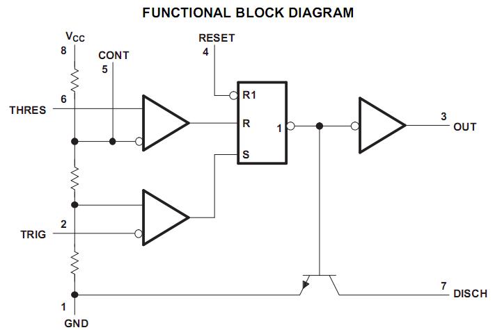
How the circuit works is relatively simple. At the time power is applied, the voltage at pin 2 (trigger) is less than 1/3Vcc. So the flip-flop is switched to set the 555 output to high. C1will charge via R1and R2. After a period of time (Tm from the diagram above) the voltage at pin 6 (threshold) goes above 2/3Vcc. At this point, the flip-flop is switched to set the 555 output to low. Furthermore, this enables the discharge function so C1will discharge via R2. After a period of time (Ts from the diagram above) the voltage atpin 2 (trigger) is less than 1/3Vcc.
So the flip-flop is switched to set the 555 output to high and the cycle repeats. Now, for an example, I want to create a pulse of 1Hz (that is, one cycle per second). It would be good to use a small value capacitor, a 0. 1uF. In faradsthis is 0. 0000001 farads. Phew. So our equation is 1=1. 4/{(R1+ [2 x R2]) x C1}. Which twists out leaving us R1=8. 2Mohm, R2=2. 9MOhm and C1is 0. 1uF. I don`t have a 2. 9MOhm resistor, so will try a 2. 7MOhm value, which will give a time value of around 0. 9s. C2in astable mode is optional, and used if there is a lot of electrical noise in the circuit. Personally, I use one every time, a 0. 01uF ceramic capacitor does nicely. Here is our example in operation: Notice how the LED is on for longer than it is off, 🔗 External reference
Related Circuits
This document outlines a basic circuit designed to power high impedance, high voltage, low current devices such as electroluminescent (EL) backlights and fluorescent tubes. The project originated from the need for a simple yet flexible inverter circuit for an...
The figure illustrates a preset outage timer circuit designed for an electric cooker. The timing range of the circuit extends from 1 hour to 12 hours, adjustable via a potentiometer (PR). The timing mode operates on a counting basis,...
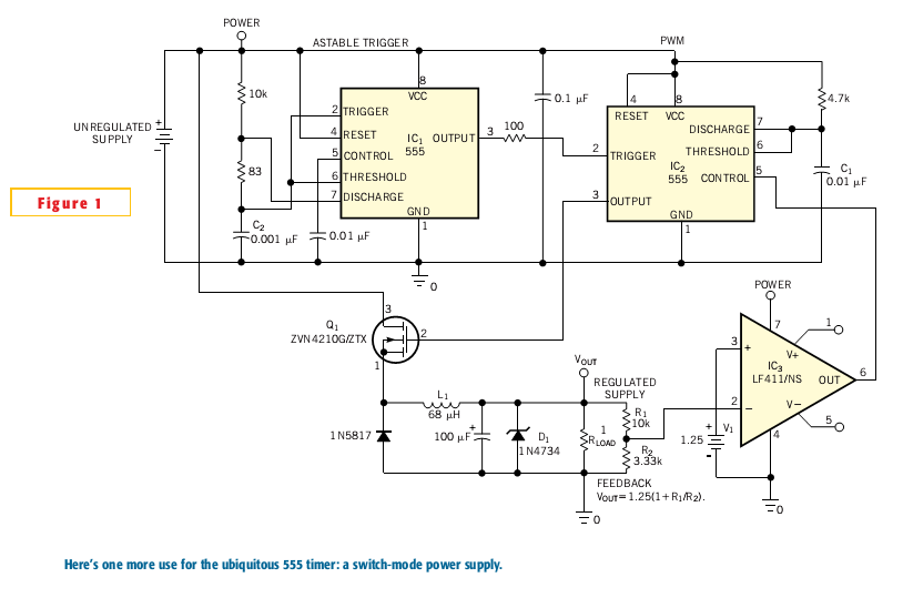
Most switch-mode power supplies utilize a PWM (pulse-width-modulated) output that is regulated through voltage feedback. A 555-timer IC can be used to generate PWM at a low cost. The circuit diagram illustrates how to convert a 555 PWM circuit...
A simple astable timer made with the 555 timer IC allows independent adjustment of the mark (on) and space (off) values. The timing circuit comprises resistors Ra, Rb, and capacitor Ct. The capacitor Ct charges through resistor Ra, which...
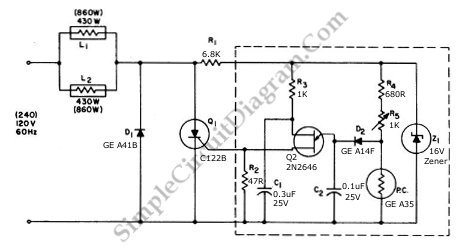
This circuit utilizes a controlled half-plus-fixed half-wave phase control method to regulate an 860-watt lamp load, allowing operation from half to full power. The circuit employs a phase control technique, which involves adjusting the phase angle of the AC...
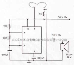
The circuit of a burglar alarm utilizing IC timer 555/556 functions as a security measure to prevent unauthorized entry into a premises. The alarm generates a loud sound when a thin wire connecting resistor R1 with pin 4 of...