
The Buck Converter

The buck converter is a crucial component in power electronics, particularly in applications requiring efficient voltage regulation and conversion. Its operation is based on the principles of energy storage and transfer, which are fundamental to switching power supplies. The transistor acts as a switch, rapidly turning on and off to modulate the voltage delivered to the load. The inductor plays a vital role by storing energy when the transistor is on and releasing it when the transistor is off, ensuring a continuous flow of current to the load.
The diode's function is equally important, as it provides a pathway for the inductor's stored energy to return to the output when the transistor is not conducting. The capacitor smooths the output voltage by filtering out voltage ripples caused by the switching action of the transistor. The relationship between the input voltage, output voltage, and duty cycle is governed by the equation Vout = Vin × D, where D is the duty cycle expressed as a ratio of the on-time to the total cycle time. This relationship allows for precise control over the output voltage by adjusting the duty cycle via a pulse-width modulation (PWM) signal.
In practical implementations, additional components such as feedback control loops may be employed to enhance voltage regulation and improve transient response. These feedback systems monitor the output voltage and adjust the duty cycle dynamically to maintain the desired voltage level despite variations in load conditions or input voltage fluctuations. Overall, the buck converter is an efficient solution for applications requiring a reduced voltage level with minimal power loss, making it widely used in battery-powered devices, power supplies, and various electronic systems.The buck converter circuit is the basis for several other similar circuits called forward converters. The buck converter circuit and the input and output voltages for this circuit are shown in Fig. 1. This circuit would be connected directly after the power transformer. From the diagram notice that this circuit is fairly simple in that it consists of a transistor, inductor, diode, and capacitor. When the transistor is turned on, power will flow directly to the output terminals. This voltage must also pass through the inductor, which will cause current to build up in it in much the same way that a capacitor charges. When the transistor is switched off, the stored current in the inductor will cause the diode to become forward bias, which will let it freewheel and allow the current to be delivered to the load that is connected to the output terminals.
The waveforms at the bottom of the diagram show the square wave of the input voltage in the top line. The waveform on the bottom line shows the effects of the inductor putting the stored current back into the circuit to the load.
This current is shown as the dashed line that occurs during the square wave off-cycle. This type of circuit is called a step-down buck converter because the output voltage will always be smaller than the input. Voltage regulation for this circuit is controlled by duty cycle. If the off-time for the duty cycle is lengthened, the average voltage to the output will be lower, and if the off-time for the duty cycle is shortened, the average power will increase.
🔗 External reference
Related Circuits
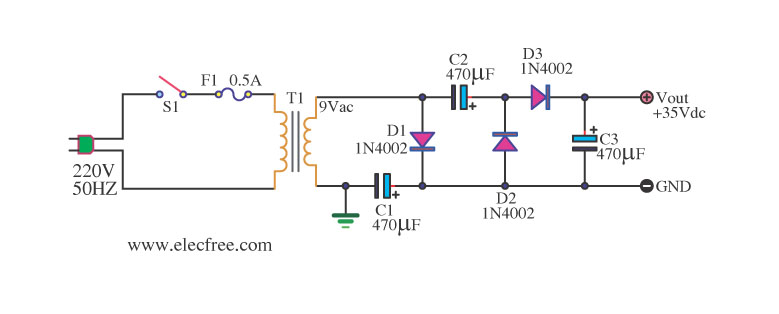
Simple AC to DC converter 9VAC to 35VDC. This is a basic example of an AC to DC converter model designed to be straightforward. It modifies 9VAC input to produce 35VDC output, depending on various factors. The AC to DC...
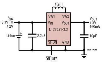
The LTC3531, LTC3531-3.3, and LTC3531-3 are synchronous buck-boost DC/DC converters that function with input voltages that can be above, below, or equal to the output voltage. The topology utilized in these integrated circuits (ICs) enables continuous power transfer across...
The AD654 is a monolithic voltage-to-frequency (V/F) converter that comprises an input amplifier, a precision oscillator system, and a high-current output stage. A single resistor-capacitor (RC) network is all that is needed to configure any full-scale (FS) frequency up...
An A/D converter circuit can be represented by a simplified schematic, which illustrates a parallel type A/D converter. The term "median" refers to the number of bits in the digital signal output. The figure displays four A/D converters utilizing...
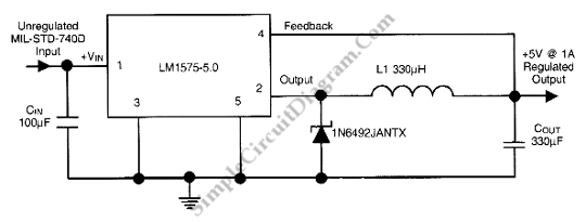
This is a 28VDC to 5VDC switching converter circuit. As a switch-mode voltage regulator, this circuit provides higher efficiency than linear regulator types. The 28VDC to 5VDC switching converter circuit operates by converting a higher voltage direct current (DC) input...
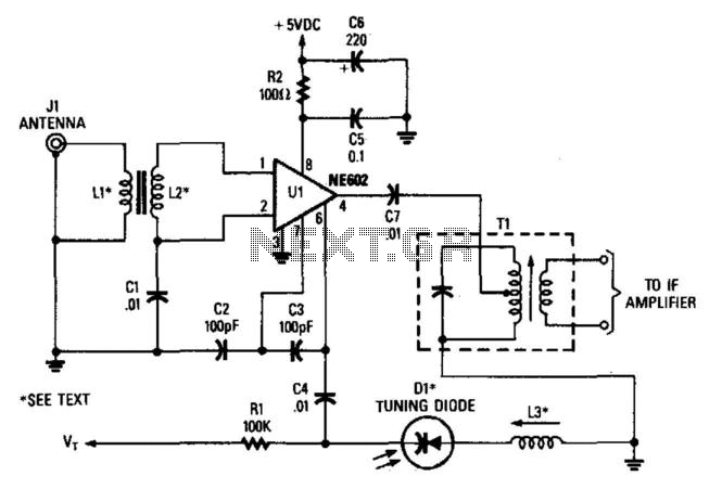
In this configuration, the NE602 serves as a frequency converter in a superheterodyne front-end setup. L1 and L2 form a broadband toroidal transformer, although a tuned transformer may also be utilized. The supply voltage ranges from +5 to +9...