
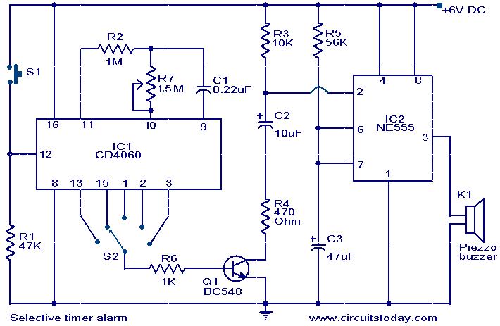
Selective timer alarm

The timer circuit described is a practical application of the IC 4060, which combines the functionalities of a binary counter and an oscillator in a single package. The oscillator frequency is critical for determining the timing intervals of the outputs. The choice of resistors R2 and R7, along with capacitor C1, sets the frequency of oscillation, which directly influences how rapidly the outputs toggle. In this configuration, the outputs from the IC 4060 are connected to the trigger input of the NE555 timer, which operates as a monostable multivibrator. This means that the NE555 will produce a single output pulse of a specified duration each time it is triggered.
The alarm mechanism is initiated when the output from the NE555 goes high, activating a connected buzzer. The duration of the alarm is adjustable, providing flexibility in the circuit's operation. By modifying the values of C3 and R5, the time the alarm remains active can be fine-tuned, allowing for various applications depending on user requirements. The behavior of Q1, which acts as a switch, is essential for controlling the trigger input of the NE555. When a high signal is received at its base, Q1 conducts, allowing capacitor C2 to charge and subsequently drop the voltage at the trigger pin of the NE555, thus initiating the timing cycle.
The IC 4060's outputs are designed to provide a series of timing intervals, with the maximum duration available at pin 3. The outputs at pins 2, 15, and 13 provide progressively shorter timing intervals, allowing for a range of timing applications from a single circuit. Adjustments to capacitor C1 can further modify the overall timing characteristics of the circuit, making it versatile for various timing needs. Overall, this timer circuit offers an efficient solution for generating timed signals and alarms in electronic applications.A timer circuit using IC 4060 is given here. The IC 4060 is a 14 stage binary counter with a built-in oscillator. R2, R7, C1 are the components that determine the frequency of the oscillator and the outputs will become high one after other and only one at a time. The last five outputs are only used here. The high pulses from the outputs are used to trigger the NE555 IC. Here NE555 is wired as a monostable multivibrator. The buzzer will produce the alarm when the output of IC2 goes high. The duration of the alarm depends on the components C3 and R5. The duration can be adjusted by varying the value of C3. The alarm will automatically turn OFF after the predetermined time. The trigger pin of IC2 will be normally positive. When the Q1 is forward biased by the positive pulse at its base from IC1, the capacitor C2 becomes charged and reduces the voltage at trigger pin of IC2. This triggers the IC. When the capacitor is fully charged the pin 2 becomes again positive. The maximum duration from timer IC 4060 will be at pin 3. The times decrease by half in the pins 2, 3, 15, and 13 respectively. The timer duration can be varied by varying the capacitor C1. 🔗 External reference
Related Circuits

The circuit utilizes a 555 integrated circuit (IC) functioning as an astable multivibrator. When a positive 9 volts is applied to pin 8, the circuit generates sound through a speaker. The connection to pin 8 is routed through a...

Have you ever accidentally left your front door ajar and had a pet escape? This circuit offers a smart solution to this problem. It is relatively simple yet serves as an excellent example. The circuit designed to prevent pets from...

False alarms caused by semiconductor failures are eliminated with this burglar alarm circuit, which is equipped with relays. Additionally, the circuit is nearly immune to false triggering. With a standby current of less than 0.1 mA, it incorporates all...
In this fire alarm circuit, a thermistor functions as the heat sensor. As the temperature rises, its resistance diminishes, and conversely, when the temperature falls, its resistance increases. At standard temperature, the resistance of the thermistor (TH1) is approximately...
The following circuit illustrates a Selective Timer Alarm Circuit based on the 4060 Integrated Circuit (IC). Features include an automatic turn-off mechanism for the alarm after a specified duration. The Selective Timer Alarm Circuit utilizes the 4060 IC, which serves...

The CMOS 4060 is a 14-bit binary counter; however, only ten of these bits are connected to output pins. The 4060 also includes two inverters, which are connected in series across pins 11, 10, and 9. Together with resistors...