
XTR105 reverse voltage and over-voltage surge protection circuit
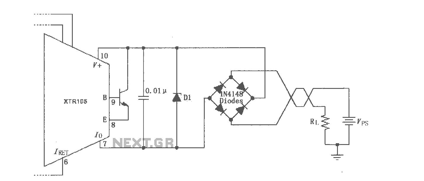
The XTR105 circuit is designed to protect sensitive electronic components from reverse voltage and over-voltage conditions that could lead to failure. The inclusion of a Zener diode, particularly one with a breakdown voltage of 36V, is critical in clamping excess voltage and preventing damage. The Zener diode can be selected from various models, such as the 1N4753A or the 1N6286A, both of which are suitable for this application.
In this configuration, it is important to ensure that the maximum supply voltage (Vps) does not exceed the minimum breakdown voltage of the Zener diode. This ensures that the Zener diode operates within its specified limits, providing effective protection to the circuit.
Furthermore, the diode bridge introduces a voltage drop of approximately 1.4V, which must be accounted for in the overall voltage supply calculations. This voltage loss affects the supply voltage available to the rest of the circuit, and therefore, the design must ensure that the remaining voltage is sufficient for proper operation of the XTR105 and any connected components.
Overall, careful selection of the Zener diode and thorough consideration of voltage drops in the circuit are essential for achieving reliable surge protection in applications utilizing the XTR105.Shown for the XTR105 reverse voltage and over-voltage surge protection circuit. Zener diode is 36V, or choose 1N4753A 1N6286A. Maximum Vps must be less than the minimum zener diode breakdown voltage of the diode bridge produce the loop supply voltage of 1.4V loss.
Related Circuits
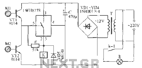
The Rw A77S power system utilizes an integrated circuit fabrication design featuring a dual touch light switch. It employs a transformer (T) for power conversion, a rectifier (VD4), and a capacitor (C) for filtering, resulting in a 12V DC...
This is a line follower designed to trace grid-type tracks. It features five line sensors for tracking the line. This arrangement of five sensors has proven effective, having been used multiple times with successful results. The device is named...
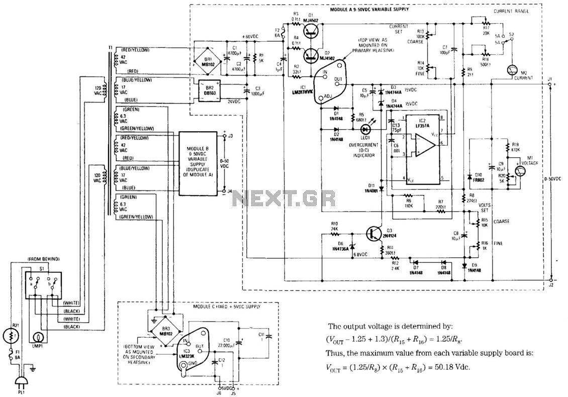
The design's value is derived from the use of IC1, an LM317HVK adjustable series-pass voltage regulator, which provides broad-range performance along with voltage-setting and current-limiting functions. The input to IC1 is sourced from the output of BR1, which is...
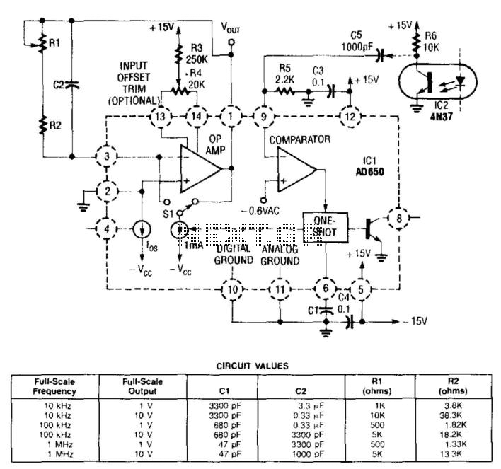
In this circuit, the input from the IC2 optocoupler is connected to the comparator input of the AD650 (Analog Devices or Maxim Electronics) voltage-to-frequency (V/F) converter. This converter internally generates a pulse that is sent to the operational amplifier,...

This is a rather sensitive circuit which will detect minute variations of a magnetic field, particularly the Earth magnetic field. The principle is based on an audio beat tone generated by two identical oscillators. These must be built in...
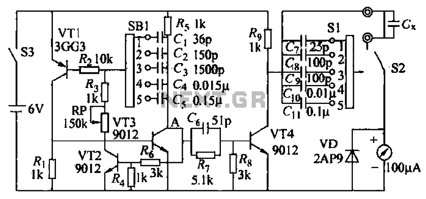
A capacitive measuring instrument is a direct reading device that measures the capacitance of a circuit. This instrument is capable of measuring capacitance values ranging from a few picofarads to 0.1 microfarads, with specific ranges of 25 pF, 100...
Warning: include(partials/cookie-banner.php): Failed to open stream: Permission denied in /var/www/html/nextgr/view-circuit.php on line 713
Warning: include(): Failed opening 'partials/cookie-banner.php' for inclusion (include_path='.:/usr/share/php') in /var/www/html/nextgr/view-circuit.php on line 713