
The Human Theremin with ir distance sensor

For this theremin, two distance sensors are required—one to manage the volume and the other to adjust the pitch. The project utilizes simple infrared reflectivity sensors that measure the amount of infrared light reflected from a nearby object, such as a player's hands. When a target approaches the IR LED and phototransistor pair, more light is reflected back into the sensor. The IR LED and phototransistor are aligned closely and parallel to each other.
The circuit for each sensor includes an IR LED, which functions similarly to a standard LED, necessitating a current-limiting resistor to regulate device current and light intensity. With a 100-ohm resistor and an approximate 1.5V forward voltage drop of the IR LED, a current of about 35mA is achieved. Although this current level is relatively high, increased light emission results in more light returning to the sensor.
The phototransistor features an exposed silicon junction, allowing infrared light to reach the sensor while other wavelengths are absorbed by the casing. Each photon that strikes the silicon junction generates a flow of electrons. As a phototransistor, this current is amplified by the transistor's current gain, resulting in a flow of approximately 10 to 100 electrons for each photon. The current flows through a 10K resistor, causing a voltage rise across the resistor, which is measured by the microcontroller's Analog to Digital Converter (ADC).
The resistor values act as adjustable parameters to achieve the desired output voltage as a hand approaches the sensor. Increasing the 10K resistor value will proportionally increase the output voltage, provided it does not exceed the +5V limit. However, this may also amplify any background infrared light, such as from natural sources. The 100-ohm resistor can be reduced to allow more current through the LED, but this will lead to faster battery discharge.
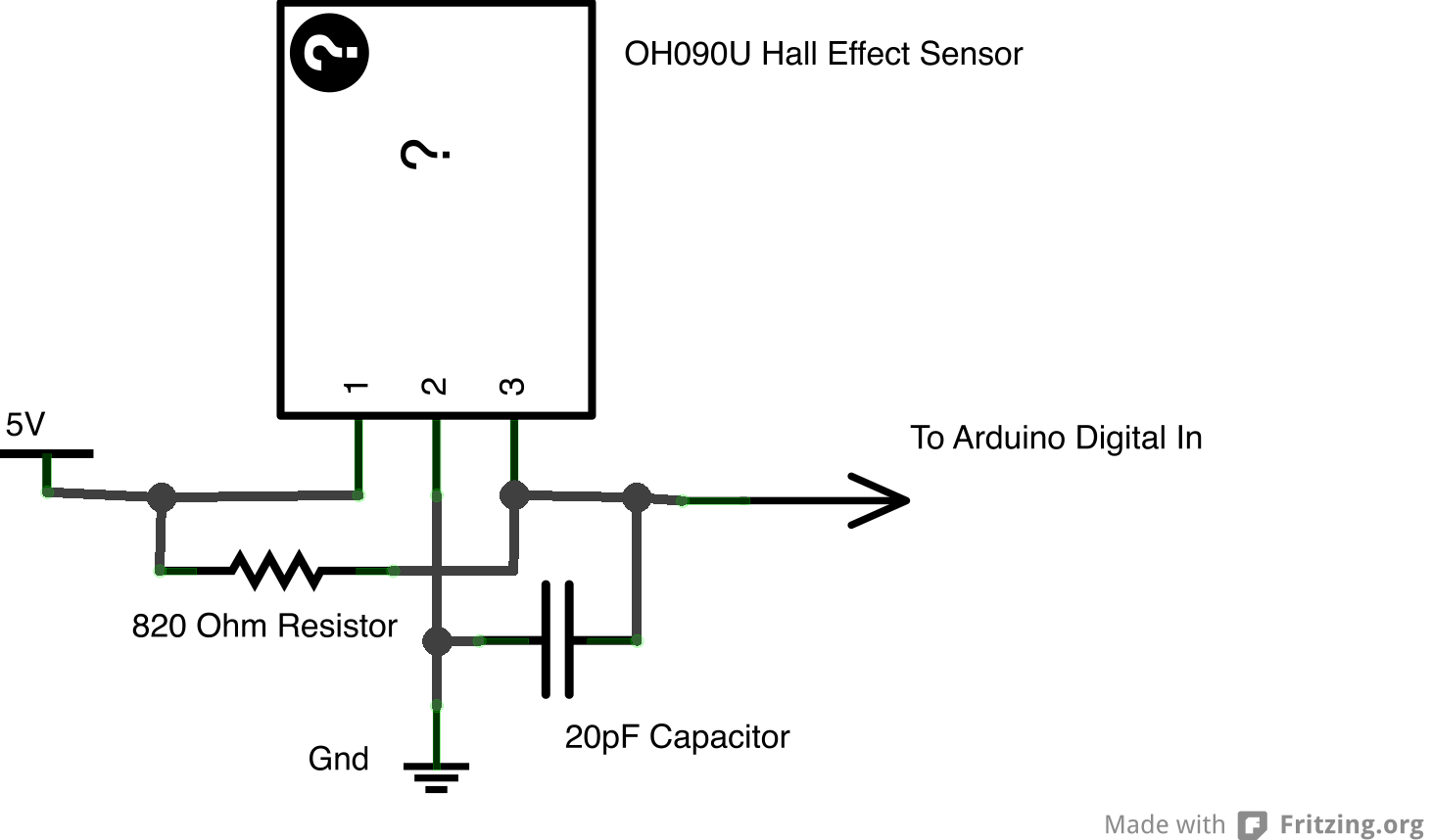
To construct the sensor, replicate the provided schematic on a solderless breadboard. Testing the sensor with a multimeter will allow for voltage readings across the 10K resistor while moving a hand near the sensor. For a more permanent solution, the components can be soldered together for durability.We always like to use Halloween as a chance to show off neat homemade electronics to the general public. In this special Halloween video tutorial, we have recreated the idea behind a musical instrument called the theremin, and built one into a Halloween costume.
This not only gives you the ability to wear a costume that is loud and very likely obnoxious, but also to have a costume that is fun for others to interact with. The project uses two infrared distance sensors, as well as PWM (Pulse Width Modulation) and a piezoelectric buzzer to create a sound, and brings together quite a few concepts to make the whole thing work. This project recreates the properties of a musical instrument called the theremin. A theremin is played without the performer having physical contact with the instrument. A "normal" theremin uses two antennas and changing electric fields to sense the position of the players hands (not unlike our previous Capacitive Proximity Sensor from last Halloween); one hand controls the pitch of the note, and the other hand controls the volume or amplitude of the note.
The idea behind this costume is to recreate the function of a theremin and build it into a Halloween costume, giving someone that approaches you while trick-or-treating the ability to wave their hands and make music with your costume like a theremin. For our theremin, we need two distance sensors: one to control the volume of the note being played, and the other to change the pitch.
We decided to build two simple IR reflectivity sensors which measure how much infrared light is reflected from a nearby target. When a target (like the player`s hands) is brought closer to the IR LED and phototransistor pair, more light is reflected back into the sensor.
As shown in the photos above, the IR LED and phototransistor are placed in close proximity and are pointed parallel to each other. The circuit we are using for each sensor looks like this: The IR LED is just like any other LED, in that a current-limiting resistor is useful to control the device current and therefore the light intensity.
With a 100 ohm resistor and the approximately 1. 5V forward voltage drop of the IR LED, we`ll have a LED current of about 35mA. That`s fairly high, but more light emitted will yield more light coming back to our sensor. The phototransistor is a device with an exposed silicon junction. When light passes through the plastic casing, most non-IR wavelengths are simply absorbed by the plastic, but the infrared light makes it to the sensor within. Each photon striking the silicon junction causes an electron to flow. Because this is a phototransistor and not a photodiode, this current is multiplied by the transistor`s current gain, so each photon may actually cause perhaps 10 to 100 electrons to flow.
This current has nowhere to go except through the 10K resistor, and as the current passes through the resistor, the voltage across the resistor rises (V=IR). This change in voltage is read by our microcontroller`s Analog to Digital Converter (ADC). The two resistor values are both "knobs" that can be adjusted to get the desired level of voltage as a hand is moved near the sensor.
Increasing the 10K value will increase the output voltage proportionally, which is fine as long as the voltage doesn`t saturate (as it can`t go above +5V). Additionally, the presence of any background IR light (such as from natural light sources) will be amplified by increasing the 10K resistor value.
The 100 ohm resistance can be made smaller to allow more current to flow through the LED, but this causes the battery to discharge faster. To assemble a sensor, complete the schematic shown above on your solderless breadboard. Test the sensor, and using a multimeter, read the voltage across the 10K resistor as you move your hand up and down.
If you would like to make your sensor more permanent, you can solder it together as 🔗 External reference
Related Circuits
The basic operation of the monitor connected to the circuit is to detect objects (obstacles) at distances ranging from a few millimeters to several centimeters. This type of circuit is utilized in various industries and hospitals. The position sensor...
The purpose of this circuit is to animate shop-windows by means of a capacitive sensor placed behind a post-card-like banner. The card is placed against the glass inside the shop-window, and the visitor can activate the relay placing his...
R1 = 470K, N1, N2 = MC14093B, R2 = 15M, T1 = 2N3906 (also compatible: PN200, 2N4413), C1-C4 = 2.2nF (NTE159, ECG159, BC557, BC157, TUP), D1 = 1N4001, Ry = Relay (12V or matching supply voltage), D2, D3 =...
Although the Arduino effectively captures incoming sensor data, executing code typically in the microsecond range, challenges arose in transmitting data between the Arduino and Max. The data transfer speed was insufficient. The focus was primarily on creative project realization...
To obtain an accurate pressure value, it is essential to eliminate offset errors. Numerous basic circuit designs are employed to remove these offset errors. Offset errors in pressure measurement systems can lead to inaccuracies in the readings, which may affect...
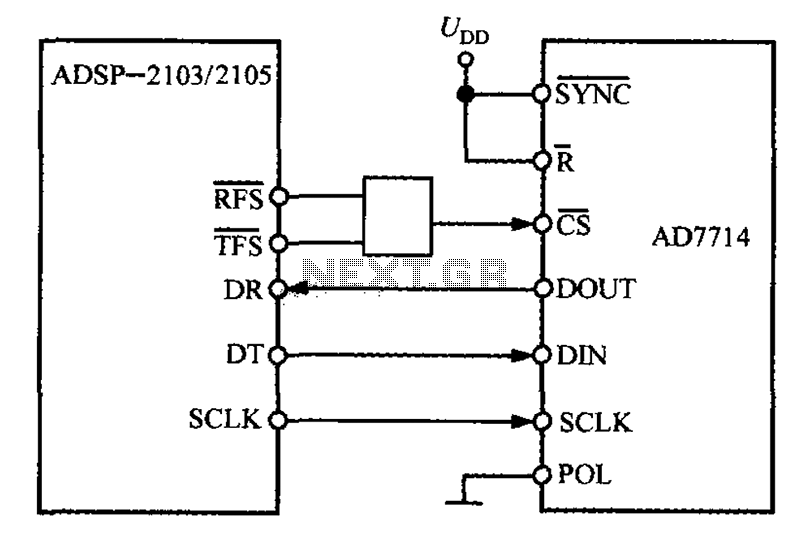
The ADSP-2103 and ADSP-2105 are digital signal processors that interface with the AD7714. When the output is active, the ADSP-2103/2105 configuration includes the RFS non-TES non-terminal set to a low level, while the SCLK terminal is configured for serial...