
The inverter circuit diagram composed of NE555
The NE555 timer is a versatile integrated circuit widely used for generating precise time delays and oscillations. In this inverter application, it operates in astable mode, producing a continuous square wave output. The frequency of oscillation, which is critical for the inverter's performance, is calculated using the formula:
\[ f = \frac{1.44}{(R1 + 2 \cdot RP1) \cdot C1} \]
Where:
- \( f \) is the frequency in Hertz (Hz)
- \( R1 \) is a fixed resistor
- \( RP1 \) is a variable resistor (potentiometer) used for fine-tuning
- \( C1 \) is the timing capacitor
To achieve a stable output of 50Hz, the values of R1, RP1, and C1 must be selected carefully. For instance, if R1 is set to 1kΩ and C1 is 100µF, adjusting RP1 will allow the user to reach the desired frequency.
The output from pin 3 of the NE555 is a square wave that toggles between the supply voltage and ground. This square wave is then utilized to drive a transformer, which steps up the voltage to 220V AC. The transformer must be rated to handle the power requirements of the load connected to the inverter.
In addition to the basic components mentioned, it is advisable to incorporate protective elements such as diodes to prevent back EMF from damaging the NE555 and other components. Capacitors may also be added to filter the output, ensuring a cleaner AC signal.
Overall, this inverter circuit is a practical solution for converting low-voltage DC to high-voltage AC, suitable for various applications, including powering small appliances and electronics. Proper design and component selection are essential to ensure reliable operation and efficiency.The inverter circuit diagram composed of NE555 is shown as the chart, and it can turn +12V DC battery voltage to 220V AC output voltage. In the circuit, NE555 circuit is the oscillator, the oscillation frequency is decided by the R1, RP1 and C1, and adjusting the resistance of RP1 in 50HZ, one way of the pulse signal output by NE555`s pin 3 is directly added..
🔗 External reference
Related Circuits
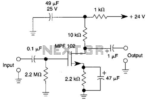
This JFET preamplifier has a gain of approximately 20 dB and a bandwidth exceeding 100 kHz. It is useful as a low-level audio amplifier for high-impedance sources. The described JFET (Junction Field Effect Transistor) preamplifier is designed to amplify low-level...
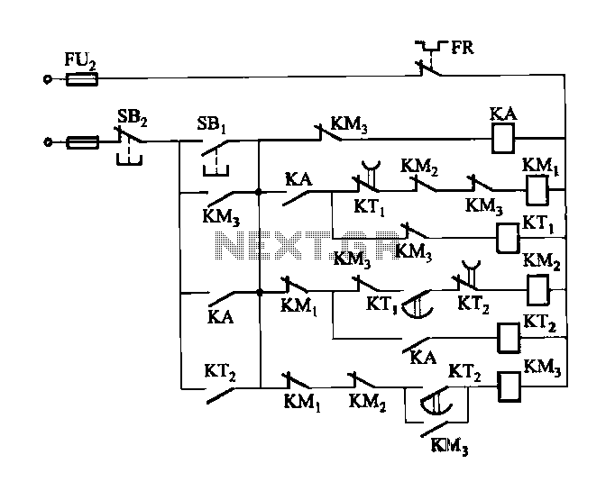
Figure 3-118 illustrates an automatic acceleration control circuit. This circuit employs a male contactor time relay, enabling the motor to start automatically at a low speed before transitioning to high-speed operation. The automatic acceleration control circuit depicted in Figure 3-118...
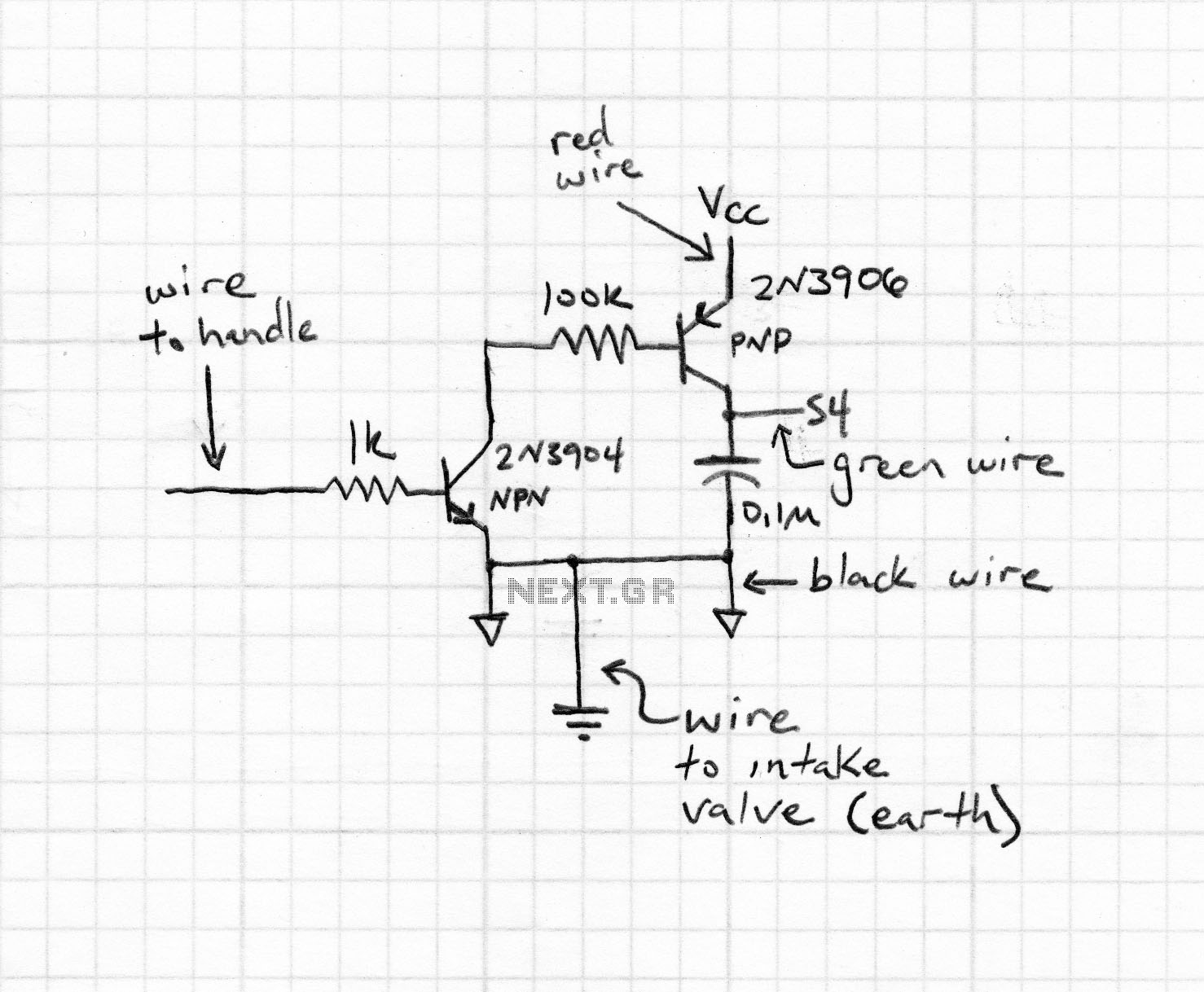
Magnetic stripe reader, electric circuit theory, logic operation. The wiring diagram does not connect the transistor in the circuit. The collector pin of the transistor connects to the tip pin of the jack. The base pin of the transistor...
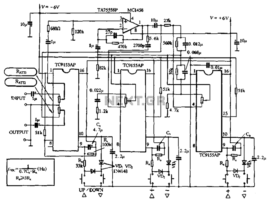
Figure 4-18 illustrates a volume potentiometer T (Xi 153AP) and a tone potentiometer T (155AP) that make up a volume and tone control circuit. This circuit includes Rx and Cx as clock oscillation elements, with values selectable based on...
The series consists of input buffers that match the output. This configuration resembles a common collector circuit with a reinforcement factor of 1. A resistor value is included to limit the current usage. The effectiveness of this circuit largely...
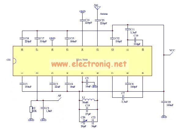
The TDA7000 features a Frequency-Locked-Loop (FLL) system with an intermediate frequency of 70 kHz, and selectivity is achieved through active RC filters. The only calibration required is for the resonant circuit associated with the oscillator, which is necessary for...
Warning: include(partials/cookie-banner.php): Failed to open stream: Permission denied in /var/www/html/nextgr/view-circuit.php on line 713
Warning: include(): Failed opening 'partials/cookie-banner.php' for inclusion (include_path='.:/usr/share/php') in /var/www/html/nextgr/view-circuit.php on line 713