
Signal Clamper Using Diode
In an electronic circuit, clamping is a technique used to restrict the voltage of a signal to a specified range. The combination of a diode and a capacitor is a common method for achieving this. In this configuration, the diode allows current to pass in one direction only, effectively blocking negative voltage excursions of the AC signal. The capacitor, connected in parallel with the load, serves to smooth out the voltage variations, providing a more stable output.
When an AC signal is applied to the circuit, the diode becomes forward-biased during the positive half-cycles, allowing the current to flow and charging the capacitor. As the AC signal transitions to the negative half-cycle, the diode becomes reverse-biased, preventing current flow and thus clamping the output voltage to a level determined by the capacitor's charge. This results in a waveform that is shifted entirely into the positive voltage region.
The capacitor's value is critical in determining the response time of the clamping circuit. A larger capacitance will result in a slower response time, leading to a more stable output but potentially less responsiveness to rapid changes in the input signal. Conversely, a smaller capacitance will allow for a quicker response but may result in a less stable output.
This clamping circuit is widely used in applications where it is essential to maintain a positive voltage level, such as in signal conditioning for analog-to-digital converters, preventing negative voltage spikes that could damage sensitive components, or in audio processing to ensure that audio signals remain within a desired range. Proper selection of the diode and capacitor components, along with consideration of the input signal characteristics, is essential for optimal performance of the clamping circuit.Diode and capacitor can be used to clamp an AC signal, shift the level into positive region for all cycle. Sometimes this condition is needed, to have positive.. 🔗 External reference
Related Circuits

This design features a simple yet effective receiver with good sensitivity and selectivity. The circuit utilizes a compact three-transistor regenerative receiver with fixed feedback, primarily based on the BC549 transistor. The tuned circuit is intended for medium wave frequencies...
The circuit diagram illustrates the LED signal amplification. The LED signal amplification circuit is designed to enhance the output signal from an LED, allowing it to drive larger loads or to be interfaced with other electronic components effectively. The primary...
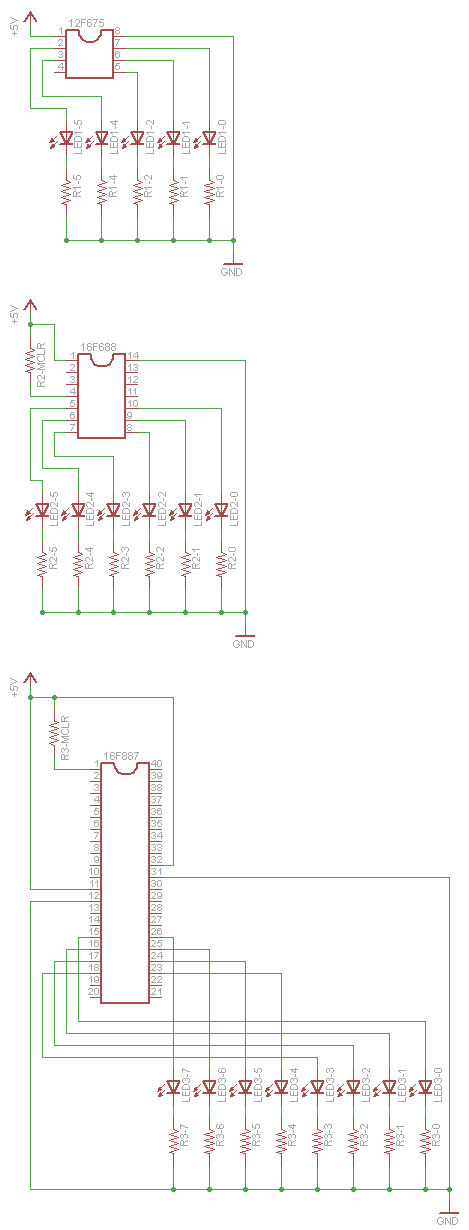
One of the drawbacks for some users is that Linux support for PIC microcontrollers is not widely known. The information is available, but the process of transitioning from writing C code to programming a chip has not been clearly...

NOPPP is a straightforward programmer designed for the PIC16C84, PIC16F83, and PIC16F84(A) microcontrollers. It connects to the parallel port of a PC. Plans for this device were published in a magazine. The NOPPP programmer is an essential tool for developers working...
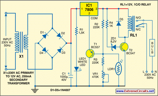
Voltage regulator ICs (78xx series) provide a steady output voltage against a widely fluctuating input supply when the common terminal is grounded. Any voltage above zero volts (ground) connected to the common terminal is added to the output voltage,...

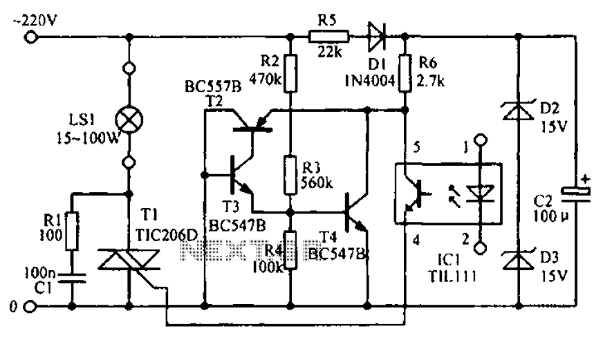
A very simple dimmer circuit with only the essentials. In this circuit, the values are given for a BT138 at 220V AC. For 115V AC, experimentation with values may be necessary. R1 can vary from one triac to another;...