
vhf rf preamp 100 175 mhz with max2633

The VHF RF preamplifier circuit utilizing the MAX2633 chip is designed to enhance signal reception in the specified frequency range. The schematic typically includes the MAX2633 as the central component, connected to an input signal source, such as an antenna. The design should incorporate proper grounding techniques to ensure stability and minimize noise. The output of the amplifier connects to the input of a receiver or other circuitry requiring amplified signals.
Key components in the circuit include passive elements such as resistors and capacitors, which are crucial for setting the gain and filtering out unwanted frequencies. The component values must be carefully selected to achieve the desired performance metrics, including the specified gain and noise figure. The PCB layout is critical; it should minimize parasitic capacitance and inductance to maintain the integrity of high-frequency signals.
The power supply circuit should provide a stable voltage within the specified range for the MAX2633, ensuring the amplifier operates efficiently. The inclusion of decoupling capacitors close to the power pins of the MAX2633 can help reduce power supply noise. The shutdown feature allows for power management, making the circuit suitable for battery-operated devices by significantly reducing power consumption when the amplifier is not in use.
This VHF RF preamplifier circuit is an excellent choice for applications requiring improved signal reception in the VHF band, particularly where low-power signals are involved, making it ideal for various radio communication scenarios.This is the diagram of VHF RF Preamp circuit 100-175 MHz with single chip MAX2633. The circuit can be used for the entire VHF broadcast and PMR band (100-175 MHz) which can be easily construct without any special test equipment. The grounded-gate configuration is inherently stable without any neutralization if appropriate PCB layout techniques are
employed. The performance of the amplifier is quite good. The noise figure is below 2 dB and the gain is over 13 dB. The low noise figure and good gain will help car radios or home stereo receivers pick up the lower-power local or campus radio stations, or distant amateur VHF stations in the 2-metres band. Due to the so-called threshold effect, FM receivers loose signals abruptly so if your favourite station fades in and out as you drive, this RF amplifier can cause a dramatic improvement.
MAX2633 are low-voltage, low-noise amplifiers for use from VHF to microwave frequencies. Operating from a single +2. 7V to +5. 5V power supply voltage, these devices have a flat gain response to 900MHz. Their low noise figure and low supply current make them ideal for receive, buffer, and transmit IF applications. MAX2633 feature a shutdown pin that allows them to be powered down to less than 1 A supply current. 🔗 External reference
Related Circuits
This circuit includes a 220µF capacitor and two diodes designed to slow down the switch-on process, thereby minimizing the output thump that occurs as the output capacitor charges through the speaker. While this feature is not essential and may...
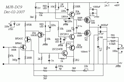
This amplifier is designed to be integrated with preamplifiers that lack a phono input. A phono input is essential for standard record players equipped with dynamic pick-ups, which remain widely used. The amplifier not only elevates the output of...
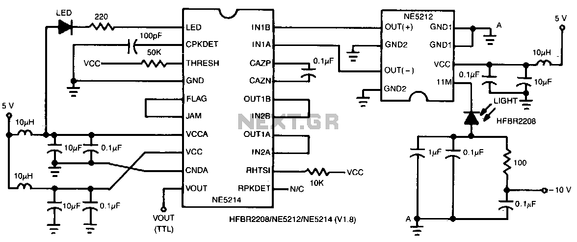
This two-chip receiver, designed for low-cost fiber optic applications at 100-M baud (50 MHz), features a minimal external component count. The receiver consists of pre-amplifier and post-amplifier integrated circuits (ICs) for enhanced stability. The preamplifier IC is characterized by...
Narrow Band Frequency Modulation (NBFM) is utilized in this 27 MHz transmitter circuit schematic. This circuit is based on the Motorola MC2833 VHF transmitter, which integrates FM modulation and narrow band capabilities into a single chip. P1 is designated...
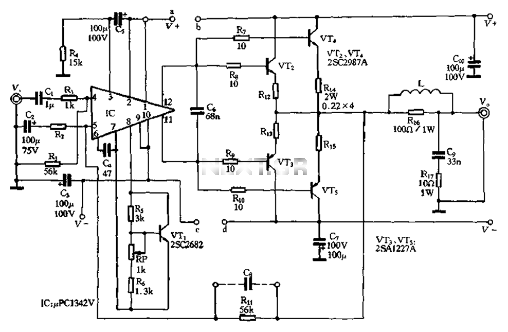
The pLPC1342V and NE are two companies involved in a tube amplifier circuit utilizing 2SA1227A and 2SC2987A transistors, achieving a maximum output power of up to 120W with a cutoff frequency of up to 500 MHz. The circuit, illustrated...
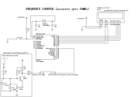
Programming of the PIC microcontroller is required prior to its utilization in this circuit, which necessitates the use of a programmer. A suitable programmer can be located by searching for "Multi-PIC Programmer." The PIC microcontroller serves as the core component...