
The most DC to DC converter step up voltage by LT1073
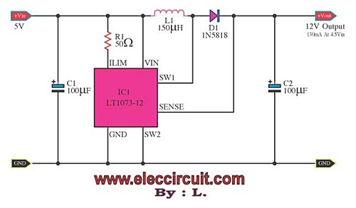
To convert the 1.5V from a single AA battery to a higher voltage of 5V while maintaining a current output of up to 100mA, a boost converter circuit can be implemented. A typical boost converter consists of an inductor, a switch (usually a transistor), a diode, and a capacitor.
The operation begins with the switch being closed, allowing current to flow through the inductor, which stores energy in the form of a magnetic field. When the switch opens, the inductor releases its stored energy, causing the voltage across its terminals to increase. This higher voltage is then directed through the diode to charge the output capacitor, which smooths the output voltage to a steady 5V.
An important aspect of the design is the selection of components. The inductor must be chosen to handle the required current without saturating, while the diode should have a low forward voltage drop to ensure efficiency. The output capacitor should be rated for a voltage higher than 5V and have a sufficient capacitance to maintain output stability under load.
Additionally, a feedback mechanism is often included to regulate the output voltage. This can be achieved using a voltage divider connected to the feedback pin of a dedicated boost converter IC, which adjusts the duty cycle of the switch to maintain a constant output voltage despite variations in load or input voltage.
The efficiency of the boost converter is influenced by various factors, including the choice of components, switching frequency, and the load conditions. Proper thermal management should also be considered to prevent overheating, particularly when operating at higher currents.
Overall, the implementation of a boost converter allows for the effective utilization of a single AA 1.5V battery to power devices requiring a 5V supply, making it a practical solution in battery-operated applications.Suppose, you want to use the 5Vdc power supply levels up to 100mA, But there is only one single AA 1.5V battery. This working we need to use The DC to DC.. 🔗 External reference
Related Circuits
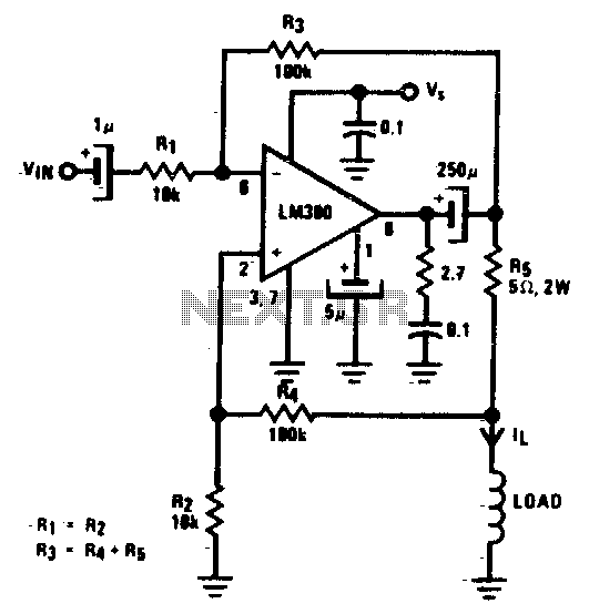
A low-cost converter is capable of supplying constant AC currents up to 1 A over variable loads. The low-cost converter is designed to provide a stable output of alternating current (AC) while accommodating fluctuating load conditions. This capability is essential...
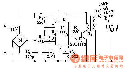
This high voltage generator is capable of producing a stable high voltage exceeding 8kV. The circuit design is straightforward, ensuring stability and reliability. It consists of a step-down rectifier, a voltage regulator circuit, an 18kHz multivibrator-type oscillator, and a...
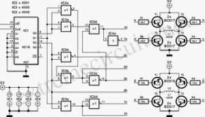
BC517 Bipolar Stepper Motor Control Circuit Diagram. Features: Each winding can carry a positive current. A bipolar motor has two windings. The BC517 bipolar stepper motor control circuit utilizes a BC517 transistor to manage the operation of a bipolar stepper...
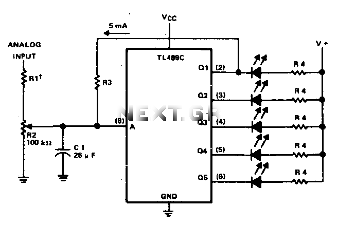
This circuit offers a visual representation of the input analog voltage level. It features a high input impedance at pin 8 and open-collector outputs that can sink up to 40 milliamperes. It is designed to drive a linear array...
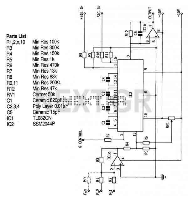
This circuit utilizes the SSM2044 integrated circuit (IC), which is a four-pole voltage-controlled filter specifically designed for electronic music applications. The on-chip voltage control of resonance facilitates straightforward interfacing with programmers and controllers. The IC is characterized by an...
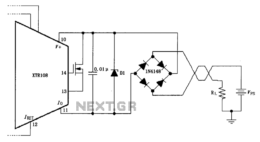
The circuit utilizes a Zener diode (D1) for overvoltage protection and a diode rectifier bridge for reverse voltage protection. The 1.4V drop across the diodes will result in a maximum voltage loss, meaning that the supply voltage (VPS) must...