
BC517 Bipolar Stepper Motor Control
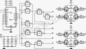
The BC517 bipolar stepper motor control circuit utilizes a BC517 transistor to manage the operation of a bipolar stepper motor. This type of motor is characterized by having two windings, which allows it to operate with positive current flowing through each winding independently. The circuit typically includes a microcontroller or a dedicated stepper motor driver IC that generates the necessary control signals for the transistors.
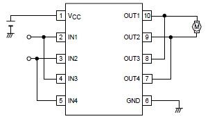
In this configuration, each winding of the stepper motor is connected to the collector of a BC517 transistor, which acts as a switch. When the microcontroller sends a high signal to the base of the transistor, it allows current to flow from the collector to the emitter, energizing the corresponding winding. By alternating the activation of the two windings, the stepper motor can be made to rotate in precise increments, providing accurate control over its position.
The circuit may also include additional components such as resistors to limit the base current to the transistors and diodes for flyback protection, preventing voltage spikes when the motor is turned off. Properly designed, this circuit enables efficient control of the stepper motor, making it suitable for various applications such as robotics, CNC machines, and other precision motion control systems.BC517 Bipolar Stepper Motor Control Circuit Diagram. Features: Each winding can carry a positive current, A bipolar motor has two windings . 🔗 External reference
Related Circuits
Cats are natural predators of rats, and the use of electronic devices to simulate meowing sounds as a repellent is an effective method. These electronic devices can produce meowing sounds at various frequencies and intervals, making them suitable for...
An alphanumeric low-cost LCD display is essential for many small and large projects to display various types of information. The Hitachi HD44780 chipset-based 16x2 character LCD is very affordable and easily available in the local market. This project covers...
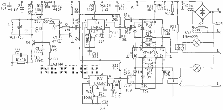
When the infrared receiver tube PH302 receives a signal from the remote control, the CX20106A selected frequency amplifier outputs a low-frequency signal. The low-level signal charges capacitor C through diodes D and R, causing the negative side potential of...
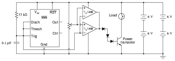
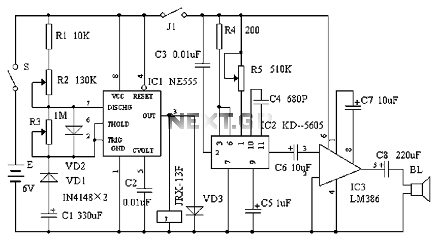
This circuit utilizes a 555 timer to generate a sawtooth voltage waveform across a capacitor, which is then compared to a steady voltage provided by a potentiometer using an operational amplifier (op-amp) configured as a comparator. The comparison of...
A simple forward-reverse motor control driver electronic circuit can be designed using the LB1948M, a two-channel low saturation voltage forward-reverse motor control driver IC. The LB1948M motor driver is suitable for use in 12V system products and can drive...
This is a tuned radio frequency receiver designed for shortwave frequencies, specifically in the 25-meter band (11.7 to 12.1 MHz). It serves as an experimental design for further investigations into the autodyne synchronous receiver, as referenced in Polyakov V....