
The most lead-acid battery charger circuit by LM317
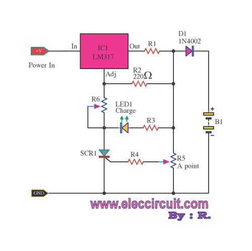
The LM317 is a versatile adjustable voltage regulator that can be effectively utilized in designing a lead-acid battery charger circuit. This integrated circuit can output a voltage range of 1.25V to 37V, making it suitable for charging both 6V and 12V lead-acid batteries with appropriate adjustments.
To design a lead-acid battery charger using the LM317, the following components are typically required: the LM317 voltage regulator, resistors for setting the output voltage, a diode for reverse polarity protection, a heat sink for thermal management, and capacitors for filtering. The circuit configuration involves connecting the LM317 in a linear regulator setup, where the output voltage is adjusted by selecting appropriate resistor values (R1 and R2) based on the desired output voltage.
For a 6V lead-acid battery, the output voltage can be set to approximately 7.2V, which is suitable for charging, while for a 12V battery, the output can be set to around 13.8V. It is essential to incorporate a current-limiting resistor or a current sensing mechanism to prevent overcharging, which can damage the battery. Additionally, a diode should be placed in series with the output to prevent reverse current flow when the charger is disconnected.
Thermal considerations must also be addressed, as the LM317 can dissipate significant heat during operation, especially under load. A suitable heat sink should be attached to the LM317 to maintain safe operating temperatures.
In summary, the LM317 provides a reliable and adjustable solution for charging lead-acid batteries, with a simple circuit design that can be tailored to meet the specific voltage and current requirements of the battery being charged. Proper component selection and configuration are crucial for the effective and safe operation of the charger.When you want to build the lead-acid battery charger project for 6V battery or 12V. Although there are many methods to choose from. I like using IC LM317.. 🔗 External reference
Related Circuits
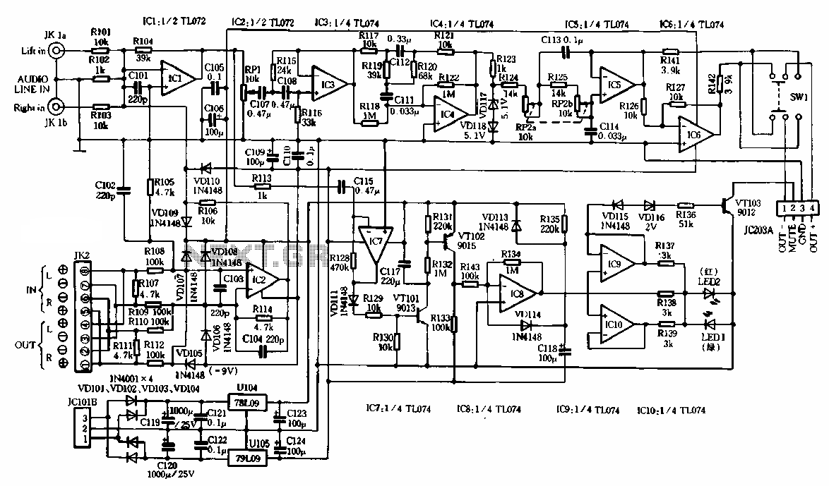
The schematic illustrates the subwoofer amplifier stage, specifically the pre-amplifier circuit and the signal processing circuit. Notably, it features two LM3886 power ICs from the American company NS, which facilitate BTL (Bridge-Tied Load) speaker operation at an 8-ohm impedance...

This stereo balance indicator circuit diagram is designed using a few common external components. The schematic circuit is simple to build and provides a visual indication with LEDs for left, right, and center balance. Outputs from each channel are...
This is a fun and non-dangerous project for those people who like to throw projectiles magnetically. It simply works by placing a ferromagnetic projectile at one end of a coil and pulsing some power in it. The trick is...
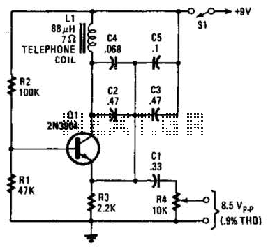
An 88 mH surplus telephone toroidal coil is utilized in a 1 kHz oscillator. It can provide up to 8 V peak-to-peak into a high-impedance load. The total harmonic distortion (THD) is 0.9%. The circuit employs an 88 mH toroidal...
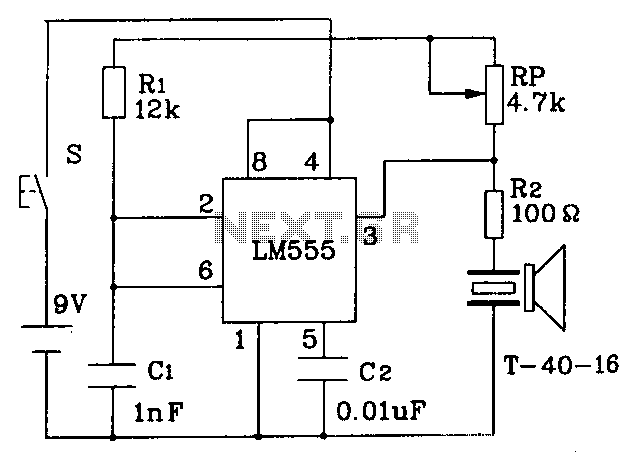
The circuit operates at a distance of 3 feet from the oscillating pulse output of a 555 timer generating a 40kHz signal, driving a T-40-16 transducer to emit ultrasonic signals at the same frequency. The circuit is powered by...
This is a straightforward liquid detector that utilizes a relay to activate an evacuation valve. It can be employed for water or any conductive liquid. The liquid detector circuit operates by leveraging the conductivity of liquids to trigger a relay....
Warning: include(partials/cookie-banner.php): Failed to open stream: Permission denied in /var/www/html/nextgr/view-circuit.php on line 713
Warning: include(): Failed opening 'partials/cookie-banner.php' for inclusion (include_path='.:/usr/share/php') in /var/www/html/nextgr/view-circuit.php on line 713