
The Original 2 Phone Link Design
When handset #1 is lifted, a DC loop is formed between the handset, the 1k winding of Tx1, the ground terminal, the +12 volts terminal, and the LEDs in optocouplers OC1 and OC3. IC1, an NE556 dual timer chip, continuously pulses at output pin 9, triggering the second half of the timer chip through diode D1 to pin 4, generating ring pulses and ring tone from pin 5 via capacitors C3 and C4 to the 8-ohm windings of Tx1 and Tx2. The transistor in OC1 activates fully, pulling its collector lead low, allowing ring pulses to flow from pin 9 of IC1 through resistor R5 and transistor Q1 to the emitter of OC3, and then to its collector, energizing buzzer B2 to signal the other phone.
When the second phone is lifted off-hook, optocouplers OC2 and OC4 create a DC loop with the 1k winding of Tx2 and the LEDs in the optocouplers. The transistors in OC1 and OC2 establish a connection from the +12 volts supply to the junction of pins 12 and 8 of IC1 through diode D2, stopping the ringer and halting both the ring pulses from pin 9 and the ring tone from pin 5 for the duration of the call. Once both phones are returned to the on-hook position, all four optocouplers (OC1 to OC4) deactivate. IC1 resumes pulsing and providing ring tone, but these outputs will not affect either phone until one is lifted off-hook again for the next call.
The previously mentioned transmission bridge consists of Tx1 and OC3 along with Tx2 and OC4, as well as capacitors C5 and C6. The 1k windings prevent speech signals (AC signals) from grounding through the earth connection. The two capacitors permit these signals to pass between the handsets while blocking DC voltages from causing interference. This circuit employs a simplified version of a Stone Transmission Bridge, making it suitable for its intended purpose.This is the circuit that sparked off all the other Link Telephone Intercom designs. Originally designed back in 1996 with heavy duty relays and their contact banks, it was updated late last year with the addition of IC1 in place of a simpler transistor multivibrator, the replacement of all relays and contact banks with optocouplers, and the additi on of the two transformers as part of the transmission bridge (see explanation below) which was comprised partly of the relay coils. If you just want simple no frills` communication from one phone to another, then this is the right circuit for you!
This version is much more compact, more economic on power drain (yes, you can run it off of batteries eg: a 12 volt Gel Cell!) and has no moving parts, except for the switch hooks inside each of the phone handsets. This was one of the earliest Link designs. It works by either caller simply picking up their handset and buzzing` the other phone. There are no numbers to dial (in fact, no dial tone either just ring tone, which pulses on and off in unison with the buzzer at either end when a call is in progress.
) Let`s assume that #1 picks up their handset. This forms a DC loop between the handset, the 1k winding of Tx1, the 0v_ earth terminal, the +12 volts terminal and the leds inside OC1 and OC3. IC1 (an NE556 dual timer chip) is always on` that is, it`s always pulsing on and off at output pin 9, which then drives the second half of the timer chip on and off via D1 to pin 4, producing ring pulses, and ring tone from pin 5 via C3 and C4 to the 8R windings of Tx1 and Tx2.
The transistor inside OC1 switches on hard, taking its collector lead low, and ring pulses are fed from pin 9 of IC1 via R5 and Q1, to the emitter of OC3, through to its collector lead, and then on to the ve lead of buzzer B2, thus buzzing` the other phone. When that phone is picked up off hook, OC2 and OC4 also form a DC loop along with the 1k winding of Tx2 and the leds inside the optocouplers.
The transistors inside OC1 and OC2 now form a link` (no pun intended) from the +12 volts supply (shown at left near phone #1) through to the junction of pins 12 and 8 of IC1, via diode D2. This effectively halts the ringer, and both ring pulses from pin 9 and ring tone from pin 5 cease for the duration of the call.
When both phones are hung up back to the on hook position, all four optocouplers (OC1 to OC4) are switched off. IC1 will now resume pulsing and providing ring tone, but neither one of these outputs will have any effect on either phone handset, until one or the other is picked up off hook again, to make the next call.
The transmission bridge` mentioned earlier, comprises of Tx1 and OC3 along with Tx2 and OC4, as well as C5 and C6. Basically, the 1k windings prevent speech signals (which are an AC signal) from being grounded through the earth connection.
The two capacitors allow these signals to pass between the handsets, but block any DC voltages from interfering with them. This circuit is known as a Stone Transmission Bridge and although I have employed a simplified version of it, it`s quite suitable for our purposes.
Happy chatting on the line ©Austin Hellier 1996 - 2003. 🔗 External reference
Related Circuits
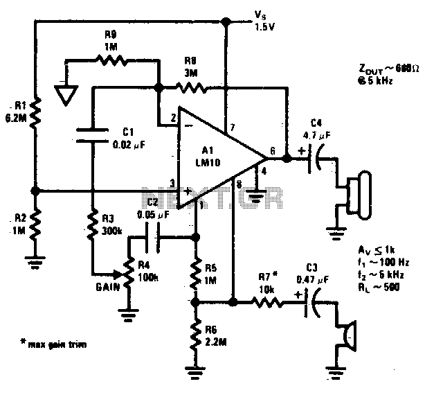
In addition to its primary function as a headphone amplifier, the circuit is suitable for various applications requiring a wide bandwidth low power amplifier. It is constructed using an operational amplifier (op-amp), with its output current enhanced by a...
The amplifier is capable of delivering around 1.5W into 8 ohm headphones, and 2.2W into 32 ohms - this is vastly more than will ever be needed in practice. The use of a 120 Ohm output resistor is recommended,...
This circuit was designed to detect when a call is incoming in a cellular phone (even when the calling tone of the device is switched-off) by means of a flashing LED. The device must be placed a few centimeters...
This circuit operates from a 5 V DC source. The described circuit is powered by a 5 V direct current (DC) supply, which is a common voltage level for many electronic devices and applications. The circuit may utilize various components...
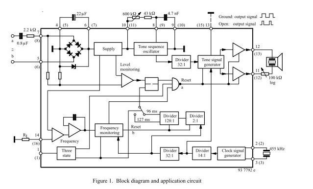
The three-tone ringing integrated circuit U4076B, in conjunction with a piezo transducer or loudspeaker, replaces the normal electromechanical telephone bell. It is operated with the ringing current frequency. The U4076B integrated circuit is designed to generate a three-tone ringing signal,...
A simple and interesting project schematic for a cell phone signal-activated LED circuit. The circuit will illuminate an LED when a call is made from a cell phone. This cell phone signal-activated LED circuit utilizes a basic principle of detecting...