
Cellular Phone calling Detector
This circuit operates on the principle of electromagnetic induction to detect the RF signal emitted by a cellular phone during an incoming call. The sensor coil, L1, is critical to the circuit's functionality. By winding 130 to 150 turns of 0.2 mm enameled wire around a 5 cm diameter former, the coil is able to capture the low-frequency electromagnetic fields generated by the phone. The placement of the circuit near the phone is essential, as the sensitivity of the detection is directly related to the proximity of the sensor to the phone's receiver.
Once the signal is detected by L1, it is fed into transistor Q1, which serves as an amplifier. This transistor is configured in a common-emitter arrangement, allowing it to amplify the weak signal from the coil. The amplified output from Q1 is then connected to the monostable input pin of the integrated circuit IC1, which is typically a timer IC such as the 555 timer. The monostable configuration allows the IC to produce a single output pulse when triggered by the incoming signal, which is essential for driving the LED.
The output from IC1 is then processed by a voltage doubling circuit composed of capacitor C2 and diode D2. This stage is crucial for ensuring that the output voltage is sufficient to drive the ultra-bright LED. The LED is chosen for its high efficiency and brightness, ensuring that the visual indication of an incoming call is prominent even in bright ambient light conditions.
The design of this circuit emphasizes low power consumption, with a standby current draw of less than 200µA. This allows for continuous operation without the need for a power switch, making it convenient for users. The overall effectiveness of the circuit can be influenced by the choice of components, particularly the sensor coil, which must be tailored to the specific application and environment in which the circuit operates.This circuit was designed to detect when a call is incoming in a cellular phone (even when the calling tone of the device is switched-off) by means of a flashing LED. The device must be placed a few centimeters from the cellular phone, so its sensor coil L1 can detect the field emitted by the phone receiver during an incoming call.
The signal detected by the sensor coil is amplified by transistor Q1 and drives the monostable input pin of IC1. The IC`s output voltage is doubled by C2 & D2 in order to drive the high-efficiency ultra-bright LED at a suitable peak-voltage.
# Stand-by current drawing is less than 200µA, therefore a power on/off switch is unnecessary. Sensitivity of this circuit depends on the sensor coil type. L1 can be made by winding 130 to 150 turns of 0.2 mm. enameled wire on a 5 cm. diameter former (e.g. a can). 🔗 External reference
Related Circuits
Can be directly connected to CD players, tuners and tape recorders. Tested with several headphone models of different impedance: 32, 100, 245, 300, 600 & 2000 Ohms. Schematic shows left channel only. B1, SW1, J1 & C3 are common...
This circuit diagram illustrates the conversion of a speaker into a microphone. When sound waves impact the diaphragm of a speaker, fluctuations occur in the coil, generating an induced voltage. This induced voltage is typically substantial but low in...
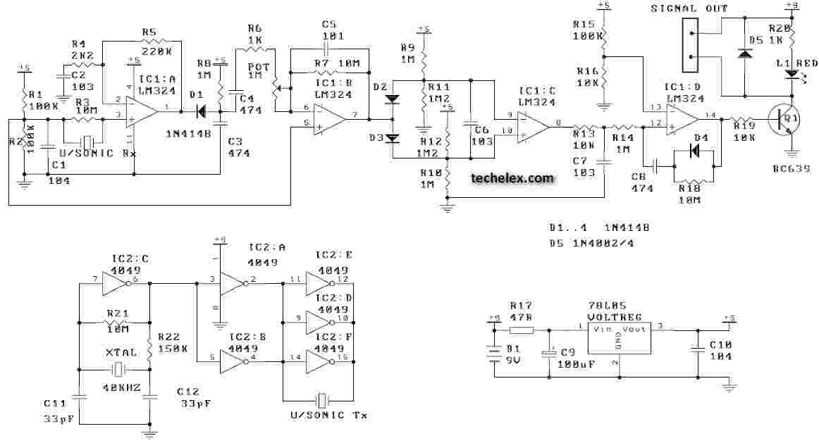
This ultrasonic movement detector circuit utilizes a crystal-locked circuit to achieve maximum performance from the ultrasonic transmitter. The detection circuit is designed to be more sensitive. It is advisable to verify all components against the parts list. Generally, it...
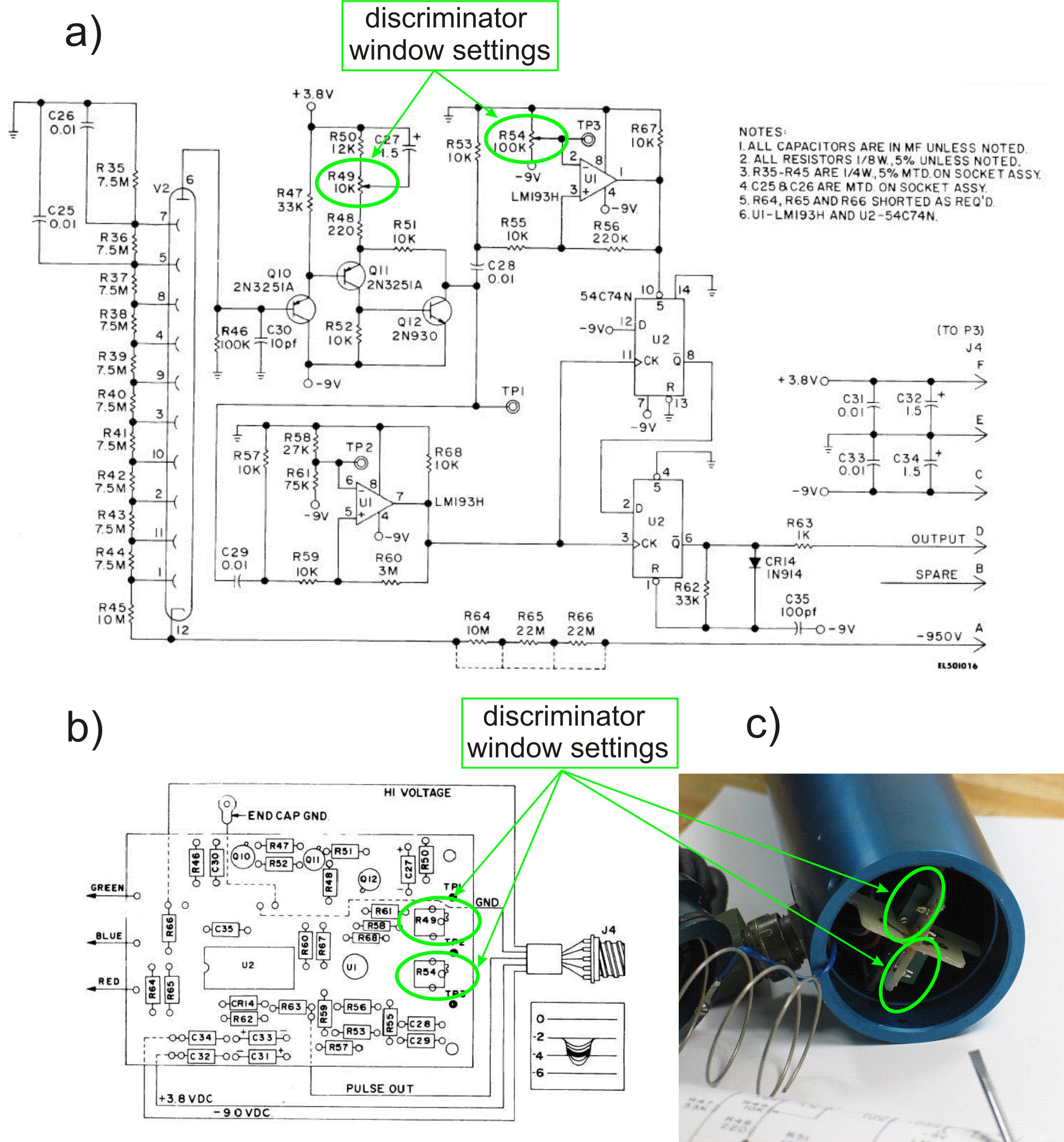
This PDF file presents the schematic diagram of a custom-built circuit designed to drive the PDR-56 probe. A JKL BXA-12579 inverter, typically used for powering cold-cathode fluorescent lamps, serves as the high-voltage power supply. The BXA-12579 generates 1,500 VAC...
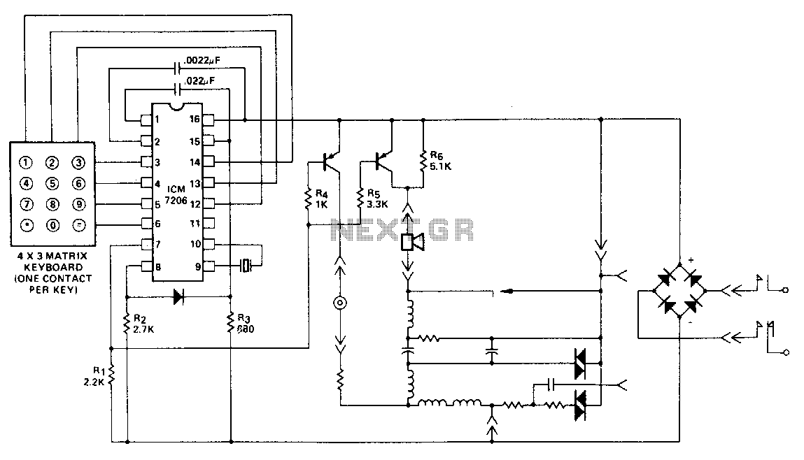
This encoder utilizes a single contact per key keyboard and implements all other switching functions electronically. A diode is positioned between terminals 8 and 15 to prevent the output from exceeding 1 volt negative in relation to the negative...
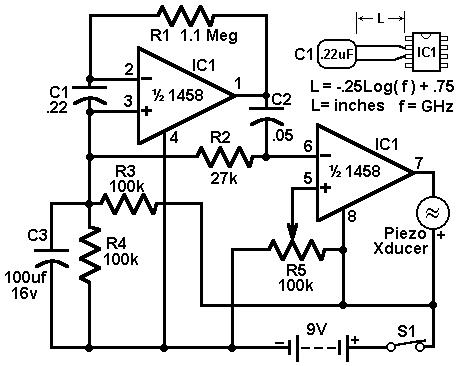
This circuit utilizes a 1458 dual operational amplifier (op-amp) to create a radar detector. Capacitor C1 serves as the sensor for the radar signal. The first op-amp is configured as a current-to-voltage converter, while the second op-amp functions as...
Warning: include(partials/cookie-banner.php): Failed to open stream: Permission denied in /var/www/html/nextgr/view-circuit.php on line 713
Warning: include(): Failed opening 'partials/cookie-banner.php' for inclusion (include_path='.:/usr/share/php') in /var/www/html/nextgr/view-circuit.php on line 713