
AD590 basic application circuit d
The AD590 temperature sensor is a precision silicon-based device that outputs a current proportional to the absolute temperature in Kelvin. Its primary application is in temperature measurement and control systems, where accurate and reliable temperature readings are essential. The output current from the AD590 can be converted to a voltage by using a resistor in series with the output. The choice of this resistor (RP) is critical as it determines the sensitivity and range of the output voltage.
In practical applications, the AD590 can be connected in series or parallel to monitor multiple temperature points within a confined area. This is particularly useful in applications such as HVAC systems, industrial process control, and environmental monitoring, where temperature variations need to be tracked at different locations. The series configuration allows for a simplified wiring scheme, while the parallel configuration can improve measurement accuracy by averaging the outputs from multiple sensors.
The integration of the AD590 with CMOS digital circuits enables advanced functionalities, such as multiplexing and switching. The use of a NAND gate as an electronic switch facilitates the selection of different temperature sensors based on control signals. This allows for dynamic temperature monitoring and data acquisition in complex systems, enhancing both efficiency and performance.
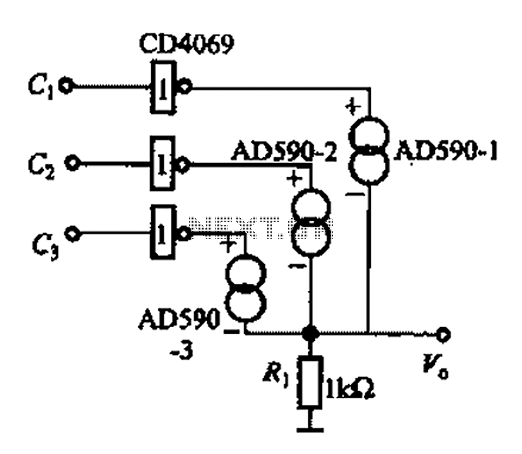
Overall, the AD590 is a versatile and effective temperature sensor, suitable for a wide range of applications that require precise temperature measurement and monitoring. Its compatibility with various electronic components and configurations makes it an ideal choice for engineers designing temperature-sensitive systems.AD590 is shown in the basic application circuit. Since the AD590 current output, series resistance to the output current is converted to voltage. Figure 1-31 (a) for the most b asic application circuit, AD590 output current Zhan. Formed on the RP as an output voltage vo, RP as an output trim. For example, when Ri + RP 1. OK, 25, the output vo 298. 15 bcA lk0, 298. 15mV. L Figure 31 (b), (c) respectively in series, parallel application of AD590, they can simultaneously in parallel or in series of three or more. AD590 series applications for multi-point temperature detection in a small space; Figure l -31 (b) the output voltage to the lowest temperature AD590 position prevail, Figure 1-31 (c), compared with the average of the output voltage of a few AD590, you can improve the multi-point temperature detection accuracy.
AD590 is very easy with the CMOS digital circuit interface, it can be connected with the gate circuits, analog switches and other electronics to make use, in Fig. 1-31 (d) is a NAND gate as an electronic switch for multi-channel temperature detection circuit, the output voltage by CL, C2, C3 side control.
For example, when cl -0, C2 1, C3 1, the output of AD590 -1.
Related Circuits

Bicycle tire leak detector circuit schematic. The circuit detects air leaks in car tires caused by sharp objects. It uses a microphone (BM) to capture the sound of escaping air, which is then converted into an electrical signal. This...
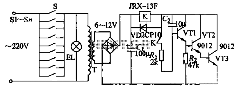
Pressing the button switch Sl-Sn activates the circuit, turning on the transformer T. The low-voltage alternating current from the secondary winding is directed to a bridge rectifier and a filter capacitor Ci, which produces a DC voltage. This voltage...
Using only a single transistor and a few passive components, a fairly sensitive peak detector circuit can be built. This peak detector circuit is suitable for various applications. The peak detector circuit utilizes a single transistor, typically configured in a...
This is a straightforward liquid detector that utilizes a relay to activate an evacuation valve. It can be employed for water or any conductive liquid. The liquid detector circuit operates by leveraging the conductivity of liquids to trigger a relay....
In certain locations near the reservoir or well, when the water level is constrained by the water towers, there is a need for simultaneous monitoring of the water towers and reservoirs as part of an automatic water control system....
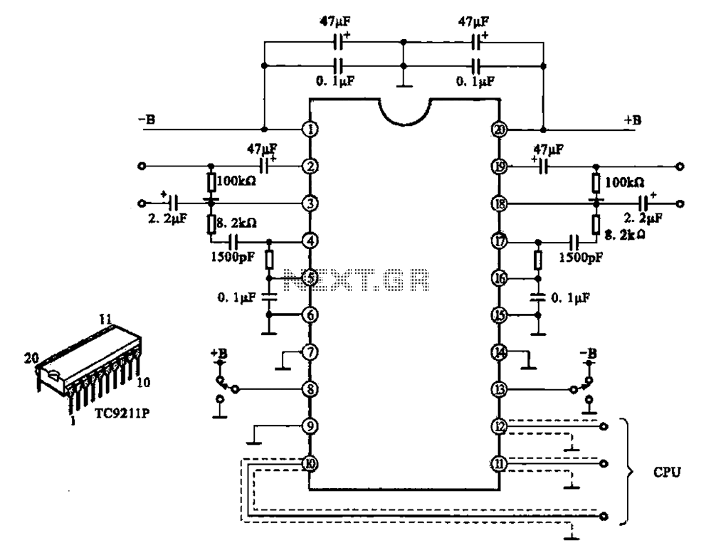
A typical electronic volume control circuit is commonly used in stereo audio devices connected through a computer (CPU). The circuit adjusts the volume of stereo signals via input and output pins. Control signals are sent to the CPU (including...
Warning: include(partials/cookie-banner.php): Failed to open stream: Permission denied in /var/www/html/nextgr/view-circuit.php on line 713
Warning: include(): Failed opening 'partials/cookie-banner.php' for inclusion (include_path='.:/usr/share/php') in /var/www/html/nextgr/view-circuit.php on line 713