
The Simple AM Broadcast Band
The crystal radio circuit operates on the principle of radio wave detection using a crystal detector, typically made from a semiconductor material. The simplicity of the design allows for easy assembly and minimal component requirements, making it an excellent project for beginners in electronics.
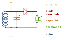
The primary components of a crystal radio include an antenna, which captures radio signals, a tuning circuit that selects the desired frequency, a detector that demodulates the signal, and a speaker or earphone for audio output. In this specific design, the antenna is crucial as it collects electromagnetic waves from the air, which are then fed into the tuning circuit.
The tuning circuit usually consists of an inductor and a capacitor, forming a resonant circuit that can be adjusted to select different frequencies. However, in this case, the circuit's design has limitations that hinder its ability to effectively tune into the medium wave AM broadcast band. This could be due to insufficient inductance or capacitance values, or possibly the placement and length of the antenna not being optimized for the desired frequency range.
The crystal detector, often a point-contact diode, rectifies the radio signal, allowing audio frequencies to be extracted. The output is then sent to a high-impedance earphone or speaker, which converts the audio signal into sound. Although the circuit is simple and inexpensive to build, the lack of effective tuning capabilities means that it may not perform well in receiving clear audio from AM stations, particularly in crowded frequency environments.
Overall, while this crystal radio circuit serves as a valuable educational tool to understand the basics of radio wave reception and signal processing, enhancements in component selection and circuit design would be necessary to improve its performance in tuning to the medium wave AM broadcast band.is a crystal radio circuit that is simple in design but ineffective in tuning to the medium wave AM broadcast band. Component: Antenna, .. 🔗 External reference
Related Circuits
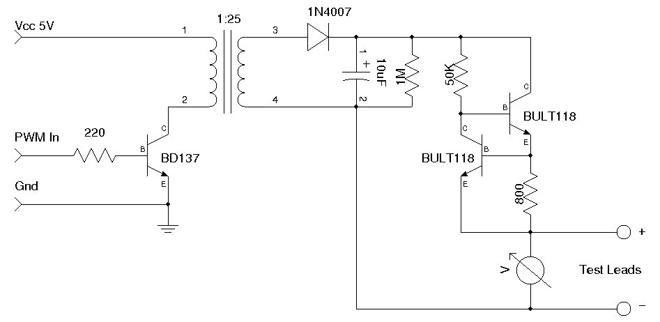
A simple Zener diode tester circuit, when combined with a PWM generator, can be utilized to measure the breakdown voltage of Zener diodes. More generally, it can also measure the breakdown voltages (e.g., BVceo, BVcbo) of BJTs (Bipolar Junction...
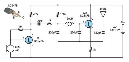
This AM transmitter is designed for simplicity and ease of construction. It utilizes a single-winding inductor that is not tapped, eliminating the need for custom winding. A readily available RF choke, such as the Jaycar Cat LF-1536, can be...
VOX is a voice-controlled switch commonly used for microphones, serving as a replacement for the traditional switching button. The actuating threshold is adjusted through the volume potentiometer. The VOX (Voice Operated Switch) circuit functions by detecting sound levels and activating...
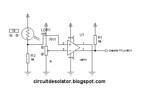
This is a common circuit block utilized in both digital and analog electronics. Its output depends on the relationship between its two input pins. One input is designated to provide the reference voltage, while the other is typically connected...
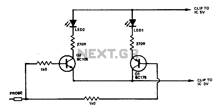
If the probe is connected to logic 0, Q1 will be activated, illuminating D1. When connected to logic 1, Q2 will be activated, illuminating D2. Any NPN or PNP transistors can be used for Q1 and Q2. Likewise, D1...
This circuit is a variable audio bandpass filter that features a low cutoff frequency adjustable from approximately 25 Hz to 700 Hz and a high cutoff frequency adjustable from 2.5 kHz to over 20 kHz. The roll-off rate is...
Warning: include(partials/cookie-banner.php): Failed to open stream: Permission denied in /var/www/html/nextgr/view-circuit.php on line 713
Warning: include(): Failed opening 'partials/cookie-banner.php' for inclusion (include_path='.:/usr/share/php') in /var/www/html/nextgr/view-circuit.php on line 713