
simple analog comparator

A comparator circuit is essential in various applications, including signal conditioning, level detection, and control systems. The fundamental operation of a comparator involves comparing two input voltages: the inverting input (often labeled as V-) and the non-inverting input (labeled as V+). The comparator outputs a high or low signal based on which input voltage is greater. When V+ exceeds V-, the output transitions to a high state, while if V- is greater, the output transitions to a low state.
The open collector output configuration of comparator ICs allows for greater flexibility in interfacing with other components. This configuration means that the output stage of the comparator can pull the output to ground but cannot drive it high. Instead, an external pull-up resistor is employed to pull the output to a high state when the comparator output is inactive. This arrangement enables multiple comparators to share a common output line, facilitating wired-AND logic in applications such as multi-sensor systems.
In practical applications, the reference voltage can be set using a voltage divider network or a precision voltage reference IC, ensuring accurate comparisons with sensor outputs. The choice of sensors connected to the comparator can vary widely, including temperature sensors, pressure sensors, and light sensors, depending on the specific application requirements.
Additionally, the response time of the comparator is a crucial factor in high-speed applications. Comparators designed for fast switching can be utilized in applications requiring rapid changes in output states, such as pulse width modulation (PWM) control or zero-crossing detection in AC signals.
Overall, the comparator circuit is a versatile and essential building block in electronic design, providing critical functionality in a wide range of applications.This is one of the common circuit blocks being used both in digital and analog electronics. Its output is dependent on the relationship of its two input pins. One of the inputs is set to give the reference voltage while the other one is commonly connected to different sensors. If the reference voltage was overcome by the input connected to the sen sor, the output of the comparator changes. The advantage of a comparator IC than an opamp used as an comparator is the property of IC comparators to be open collector output. Having this feature, we can set the output of the comparator beyond its biased voltage. 🔗 External reference
Related Circuits
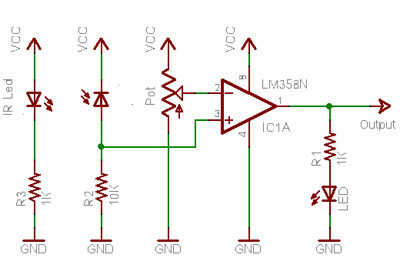
When no light is incident on the diode, it exhibits high impedance (resistance). In contrast, when light strikes the diode, its resistance decreases significantly, approaching a short circuit condition. In the absence of any object in front of the...
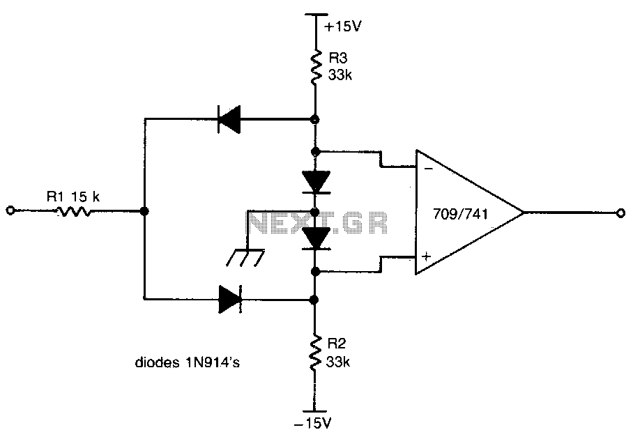
This circuit provides a positive output when the input voltage exceeds 8 volts. Within these limits, the output remains negative. The threshold for the positive output is set by the ratio of resistors R1 and R2, while the threshold...

This circuit is designed for monitoring an amateur band or a specific segment of the radio spectrum. It utilizes an NE602 mixer-oscillator chip to generate a 455-kHz intermediate frequency (IF) signal. This signal is amplified by U2 and subsequently...
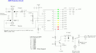
This document outlines a simple SWR (Standing Wave Ratio) protection circuit that can be easily constructed. The directional coupler and detector components are sourced from an old VHF SWR meter. It is advisable to replace the existing RF bypass...
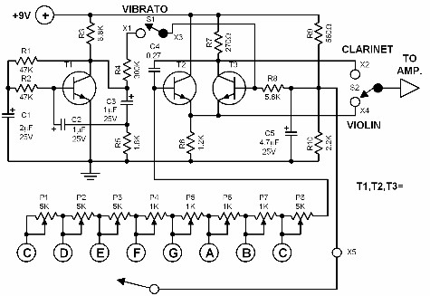
This electronic organ is simple to construct and can provide hours of enjoyment, particularly for children. The circuit is fundamentally an emitter-coupled oscillator consisting of transistors T2 and T3. A square wave voltage can be sampled from the collector...
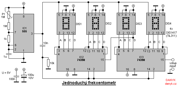
A simple digital frequency meter has various applications, serving as an experiment for beginners, laboratory equipment, or a meter integrated into certain devices. It is ideal for situations where frequency measurement and digital display are required. The frequency meter...