
Toyota Camry 2007 Car Wiring Diagram
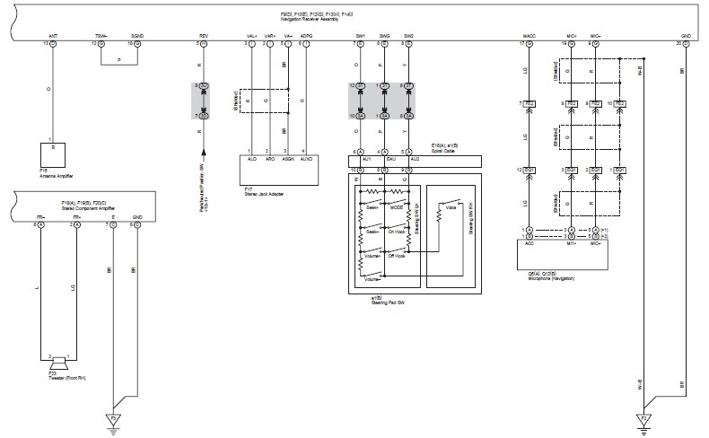
The wiring diagram for the 2007 Toyota Camry is an essential resource for understanding the electrical architecture of the vehicle. It serves as a comprehensive guide for technicians and engineers to navigate the intricate network of circuits that control various functions within the car. The diagram is segmented into different systems, such as the lighting system, power distribution, engine management, and infotainment, allowing for a systematic approach to troubleshooting and repairs.
Each circuit is represented with clear symbols and color codes, indicating the type of wire, connection points, and the components involved. For example, the lighting circuit may include details on the headlight assembly, turn signals, and interior lights, specifying the wire gauge and the connectors used. The engine management system section will illustrate the connections between the ECU, sensors, and actuators, providing insights into how the engine control system operates.
Furthermore, the diagram includes notes on fuse ratings and relay specifications, which are critical for maintaining the integrity of the electrical system. Understanding the layout and connections is vital for diagnosing electrical issues, performing modifications, or integrating aftermarket components.
This wiring diagram is an invaluable tool for ensuring that repairs and modifications are performed accurately, maintaining the vehicle's functionality and safety. It is recommended that users refer to this diagram in conjunction with other service manuals for comprehensive vehicle maintenance and repair guidance.This is the Toyota Camry 2007 wiring diagram applicable for GSV40 and ACV40 Series. This manual provides information on the electrical circuits installed on vehicles by dividing them into a circuit for each system. The actual wiring of each.. 🔗 External reference
Related Circuits
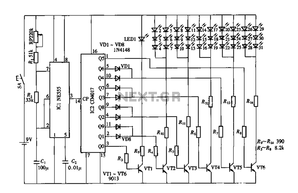
An electronic decorative peacock consists of 10 light-emitting diodes (LEDs), each of which contains multiple LEDs arranged in the tail of the peacock model. The light emission drive circuit operates the fan-shaped LEDs in a cyclic manner, emitting light...
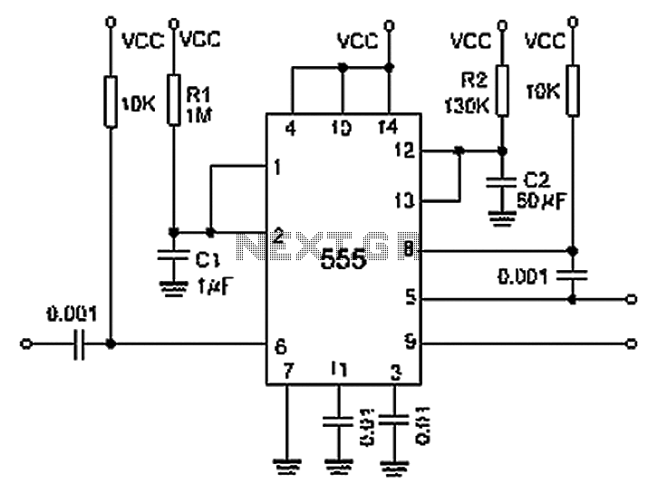
A 0.001 F coupling capacitor connects the output of the first half of a 556 timer to the input of the second half, providing an individual delay that equals the total delay. The 6-foot ground can immediately activate the...
Pulses are received by the timer from the distributor points. When the timer output is high, Meter M receives a calibrated current through R6. The meter does not... The circuit described involves a timer that receives pulse signals from distributor...
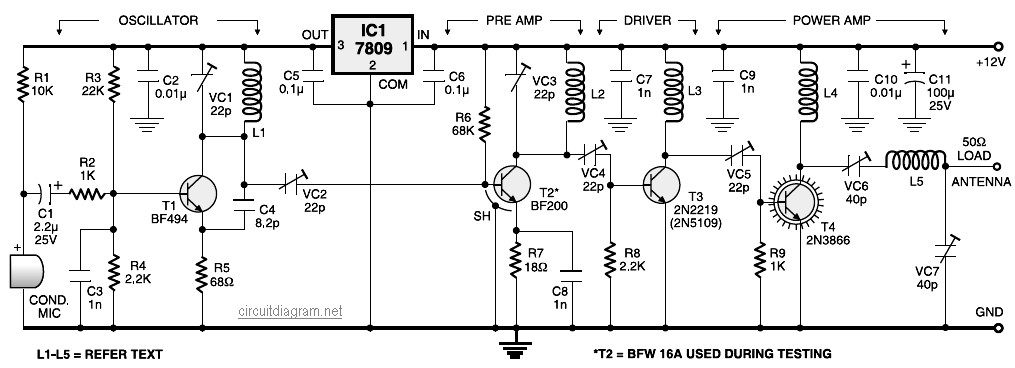
A four-stage FM transmitter circuit diagram utilizes four radio frequency stages: a VHF oscillator designed around the BF494 transistor (T1), a preamplifier based on the BF200 transistor (T2), a driver built with the 2N2219 transistor (T3), and a power...
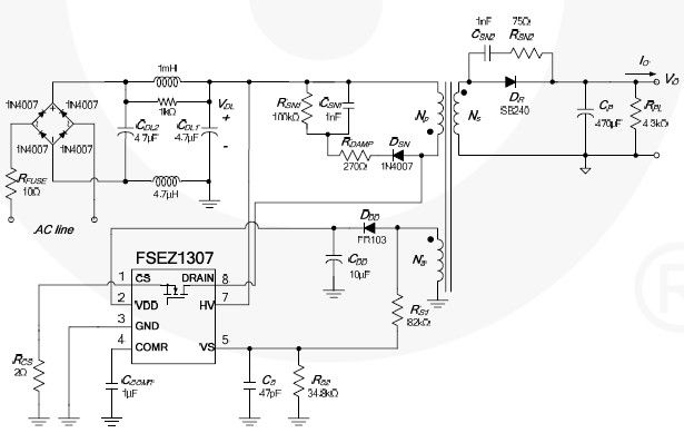
This cell phone charger circuit diagram electronic project is based on the FSEZ1307 third-generation primary side regulation (PSR) PWM controller integrated circuit. The FSEZ1307 cell phone charger can be used for battery charger applications for devices such as cellular...
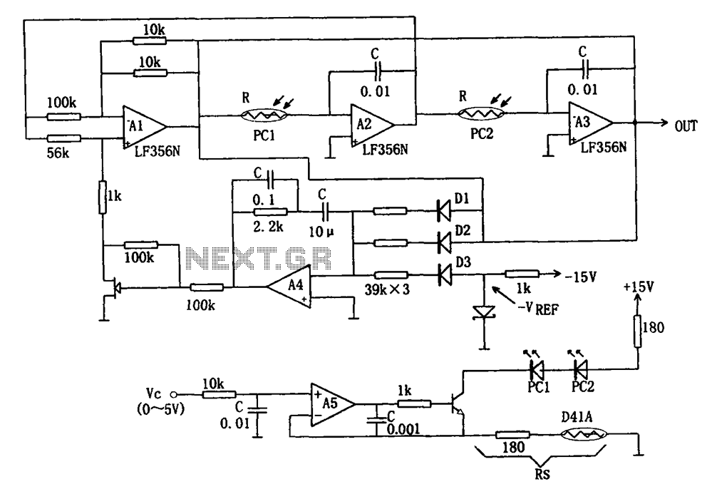
The wideband sinusoidal voltage-controlled oscillator circuit is designed such that the oscillation frequency is determined by an integrating resistor R and a capacitor C. The voltage-controlled oscillator is constituted by the applied control voltage Vc and a control resistor...