
The Stunning Camera Circuit

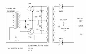
The circuit schematic outlines the basic functionality of a camera's flash system while highlighting the importance of understanding high-voltage components. The circuit consists of several key elements: a power source, ground connections, switches for the flash functions, and a large capacitor that stores energy for the flash.
In the idle state, the circuit is open, preventing any current flow. The activation of either the charge flash or release flash switches closes the circuit, allowing current to flow from the power source through the circuit components. The flash capacitor, once charged, discharges rapidly when the camera takes a picture, producing a bright flash needed for capturing images in low-light conditions.
Safety precautions are critical when dealing with the charged capacitor. The recommendation to discharge the capacitor with an insulated screwdriver highlights the potential hazards associated with high-voltage components.
The modification of replacing the large capacitor with an SPST switch is a significant alteration in the circuit design. This change allows for a continuous flow of current, which may be necessary for specific applications where constant illumination is required, as opposed to the brief burst of light provided by the flash.
Understanding these components and their interactions is vital for anyone working with high-voltage circuits, as improper handling can lead to dangerous situations. Proper circuit design and safety measures should always be prioritized in electronic projects, especially those involving significant voltage and current levels.The schematic for this project is not terribly complex, however it is very important that you understand the circuit board and how it operates because of the high voltages that are generated. Below is a `rough draft` schematic of the camera used for this project. The schematic seen above isn`t complete, however the general idea of the circuit is seen within it. The way it works is during the idle state when nothing is being pressed, nothing happens electrically. This is because power and gnd have no way of getting to each other. When either the charge flash or release flash switches are triggered this fact changes and cool things start happening.
Either a picture is taken or the flash capacitor charges. This is a very large capacitor. It can be dangerous when fully charged, enough so that you should definitely discharge it by touching both leads with the tip of a screwdriver (with an insulated handle). The reason such a large capacitor is needed is because of the large amount of current necessary to create the bright flash seen when a photo is taken.
This switch is triggered right as a photo is to be taken. The actual switch cannot be seen unless you take apart the camera. Then you`ll see that the button used to take the picture actually does two things; takes the picture & releases the flash simultaneously. This is another push button that you hold down to charge the capacitor. In this project we`ll instead remove the capacitor and use a normal SPST switch so as to allow constant current flow where the capacitor used to be as opposed to momentary current flow when the flash button is pressed.
🔗 External reference
Related Circuits

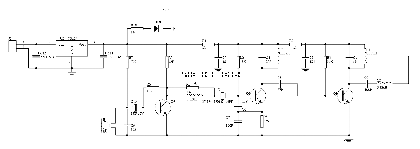
The circuit depicted utilizes the UPC1651 integrated circuit produced by NEC Corporation of Japan. It offers high gain and stability, ensuring optimal performance for microphones. The design incorporates an FM transmitter circuit. The system employs a flexible antenna measuring...
The circuit receives its input from the zero-crossing detector, which generates a 0-to-1-to-0 pulse to set the R-S flip-flop and activate the ramp circuit (A to Ramp) to initiate the timing ramp ascent. The described circuit operates by utilizing a...
A car inverter, also known as a power converter or power inverter, is a device that converts 12V DC from a vehicle’s electrical system into 220V AC for general electrical use. It serves as a convenient power adapter for...
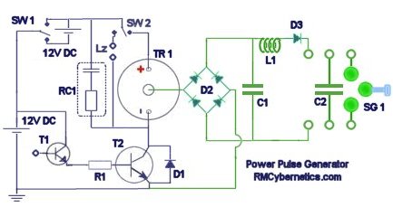
The diagram illustrates a series connection of cell diode capacitors, each rated for an increasing voltage of 300 V. This configuration generates a high DC voltage supply of 40 kV, which can be utilized for various experimental applications. With...
A wireless hands-free telephone device circuit diagram is presented below. The wireless hands-free telephone device circuit diagram typically comprises several key components that work together to enable hands-free communication. The primary components include a microphone, speaker, Bluetooth module, power supply,...
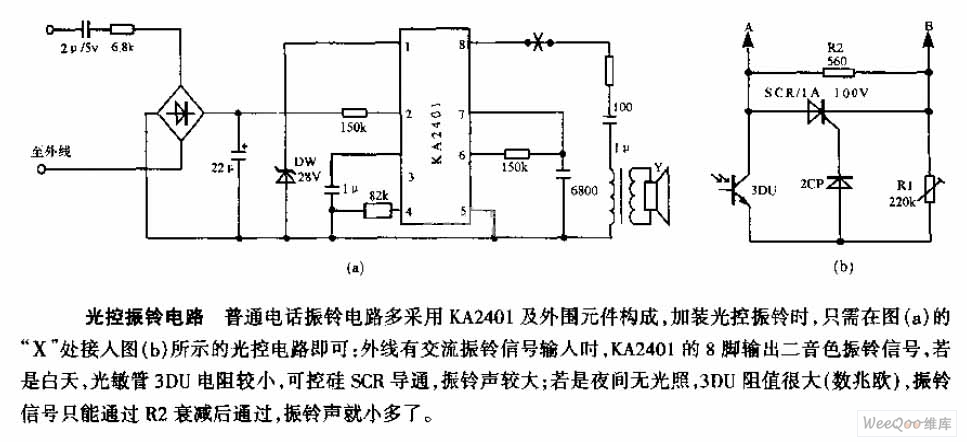
The average telephone ring circuit consists of the KA2401 integrated circuit and its associated peripheral components. To integrate a light-operated ring circuit, connect the designated part X in the provided diagram (picture a) to the light-operated circuit shown in...
Warning: include(partials/cookie-banner.php): Failed to open stream: Permission denied in /var/www/html/nextgr/view-circuit.php on line 713
Warning: include(): Failed opening 'partials/cookie-banner.php' for inclusion (include_path='.:/usr/share/php') in /var/www/html/nextgr/view-circuit.php on line 713