
A circuit diagram of a wireless hands-free telephone device
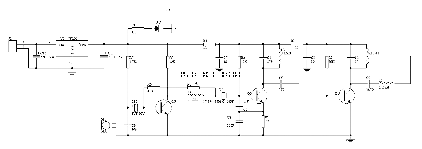
The wireless hands-free telephone device circuit diagram typically comprises several key components that work together to enable hands-free communication. The primary components include a microphone, speaker, Bluetooth module, power supply, and control circuitry.
The microphone captures the user's voice and converts it into an electrical signal. This signal is then processed by the control circuitry, which may include an operational amplifier for signal conditioning. The processed audio signal is transmitted wirelessly via the Bluetooth module, which allows for connectivity with a compatible mobile phone or other communication devices.
On the receiving end, the Bluetooth module decodes the incoming audio signal and sends it to the speaker, which converts the electrical signal back into sound waves, allowing the user to hear the other party. The power supply, often a rechargeable battery, provides the necessary voltage and current to power the entire circuit, ensuring that all components operate effectively.
Additional features may include volume control, LED indicators for connection status, and noise cancellation circuitry to enhance audio clarity. The layout of the circuit should be designed to minimize interference and optimize performance, ensuring reliable hands-free communication in various environments. Overall, the wireless hands-free telephone device circuit diagram illustrates a sophisticated integration of components that facilitate convenient and efficient communication.A wireless hands-free telephone device circuit diagram as follows:
Related Circuits
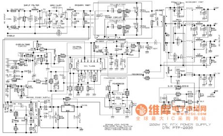
This example presents a switch DC regulated power supply circuit designed for buck-mode +5V applications. It consists of a power supply circuit, an impulsator, a voltage sampling or pulse width modulation circuit, and a buffering driver circuit, as illustrated...
This example describes the use of HS101 and HS201 radio transmitter and receiver modules to control rotating color lights, functioning as a multi-channel radio remote control device suitable for small dance floors or home use. Users positioned at any...
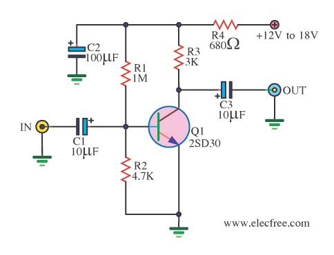
When there is a need to amplify audio signals from various sources before they reach a custom amplifier, a preamplifier (or preamp) is typically employed. This document suggests a specific circuit that is interesting due to its use of...
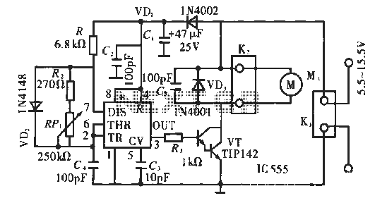
The circuit operates using pulse position modulation, which is a method distinct from the more commonly utilized pulse width modulation for speed control. A 555 timer is employed as a square wave modulator, generating output pulses with a fixed...
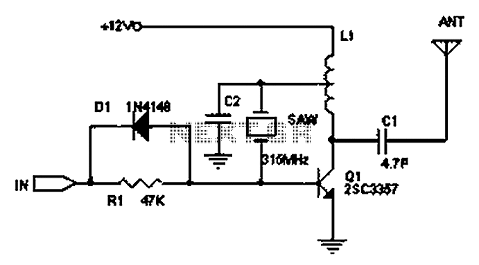
The circuit principle involves the use of an LC oscillator, which typically experiences significant frequency drift. Surface Acoustic Wave (SAW) devices have emerged as a solution to this issue, offering frequency stability comparable to that of crystal oscillators. SAW...
This intelligent electronic lock circuit is constructed using only transistors. To unlock this electronic lock, the user must press tactile switches S1 through S4 in sequence. For added security, these switches can be labeled with different numbers on the...