
Transistorized flasher
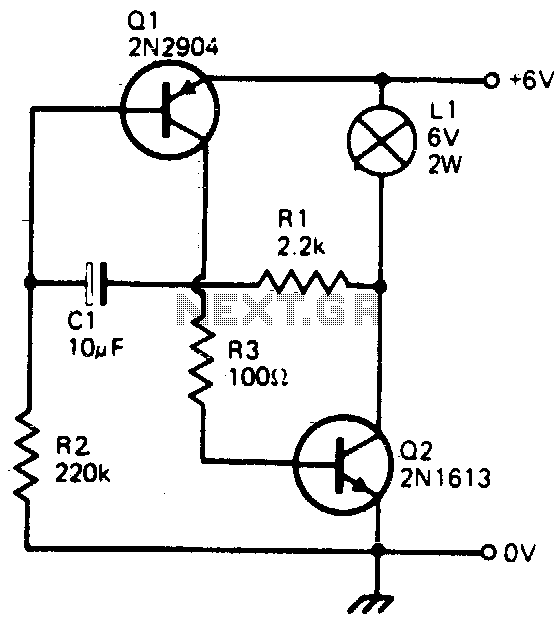
The circuit described utilizes a basic transistor switching mechanism to control the flashing of a 6-volt lamp. The key components include two transistors, a capacitor (C1), and the lamp itself. The operation of the circuit hinges on the charge and discharge cycle of the capacitor, which dictates the flashing frequency of the lamp.
When power is applied to the circuit, capacitor C1 begins to charge through a resistor. As the voltage across C1 rises, it eventually reaches a threshold that turns on the first transistor. This action allows current to flow through the lamp, causing it to illuminate. The brightness and duration of the lamp's illumination are influenced by the capacitance value of C1 and the resistance in the charging path.
Once the capacitor reaches its maximum charge, it begins to discharge, causing the voltage to drop. When the voltage falls below a certain level, the first transistor turns off, cutting off the current to the lamp. At this stage, the second transistor is also biased off, ensuring that no current flows through the circuit while the lamp is off. This design is particularly power-efficient, as current is only drawn during the lamp's on state.
The flashing rate can be adjusted by changing the value of capacitor C1 or the resistor in the charging circuit. A larger capacitor will result in a slower flashing rate, while a smaller capacitor will increase the frequency of the flashes. This circuit is suitable for applications where visual signaling is required, such as in warning lights or decorative lighting.This simple circuit will flash a 6 volt lamp at a rate determined by the size of capacitor CI. It is most economical on power as it only draws current when the lamp is on When the lamp is off, both transistors are biased off. 🔗 External reference
Related Circuits

This is a simple LED flasher project that utilizes a common 555 timer integrated circuit (IC) for its operation. It is configured in astable mode, which means its output functions as a square wave oscillator. Two LEDs are connected...

This LED flasher circuit utilizes a 555 timer integrated circuit (IC). The circuit diagram is straightforward and requires only a few external components. When operational, the red LEDs will flash sequentially at a predetermined frequency, similar to the indicators...

A low-drain circuit powered by a 1.5-V cell utilizes National LM3909 flasher integrated circuits (ICs) to replicate the "whooper" sounds characteristic of electronic sirens found in some city police cars and ambulances. Two flashers are necessary to create the...

This LED flasher circuit is similar to the previous transistor-based LED flasher but utilizes a 555 integrated circuit as the primary component. The schematic diagram illustrates an LED flasher circuit that produces alternating LED flashing, with distinct flashing periods...

This circuit operates at 230V and can be utilized for party decoration purposes. It is sourced from an old circuit book titled "100 Circuit Book." The components include DIAC ER 900 and TRIAC BTW 11-400. The circuit is designed to...
The circuit was taken from an old Elektor electronics magazine and is a compact design suitable for generating high-intensity lighting effects during festivals, parties, and gatherings. Diodes D1 and D2, along with capacitors C1 and C2, form a voltage...