
DC servo motor circuit design using A3952S motor driver
The described DC servo motor circuit is designed to control the motion of a servo motor efficiently. The core of the design is a single integrated circuit (IC), which simplifies the control mechanism while maintaining functionality. The IC typically serves as a driver, regulating the power supplied to the motor based on input signals.
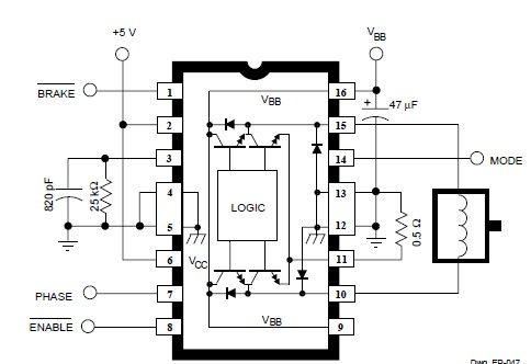
In the schematic, the connections to the PHASE terminal are crucial for enabling bidirectional control of the motor. By adjusting the signal at this terminal, the direction of the motor's rotation can be reversed. This feature is particularly useful in applications requiring precise control over rotational direction, such as robotics or automated systems.
The circuit also incorporates several passive components, including resistors and capacitors, which serve to filter signals and stabilize the operation of the IC. These components help mitigate noise and ensure smooth transitions between different operational states of the motor.
When the motor experiences abrupt directional changes, it generates back EMF, which can lead to sudden spikes in current. The design must account for this phenomenon to protect the circuit and ensure reliable operation. The current generated by back EMF is influenced by the speed and load conditions of the motor, necessitating careful consideration during the design phase to avoid potential damage to the components.
Overall, this DC servo motor circuit is a versatile solution, suitable for a range of applications in electronic projects, providing effective control and reliability in motor operation.This simple DC servo motor circuit design that can be used in various electronic projects. As you can see in the circuit schematic this Dc servo motor driver schematic circuit use just one integrated circuit and other few external electronic components. With bidirectional dc servo motors, the PHASE terminal can be used for mechanical direction c ontrol. Similar to when braking the motor dynamically, abrupt changes in the direction of a rotating motor produce a current generated by the back EMF. The current generated will depend on the mode of operation. 🔗 External reference
Related Circuits
You can play this game alone or with your friends. The circuit comprises a timer IC, two decade counters and a display driver along with a 7-segment display. The game is simple. As stated above, it is a scoring...
The circuit of the unit is fairly simple, but is a bit irksome to set up. The reason is that obtaining matched FETs is not easy, so I had to make sure that the circuit would work with off-the-shelf...
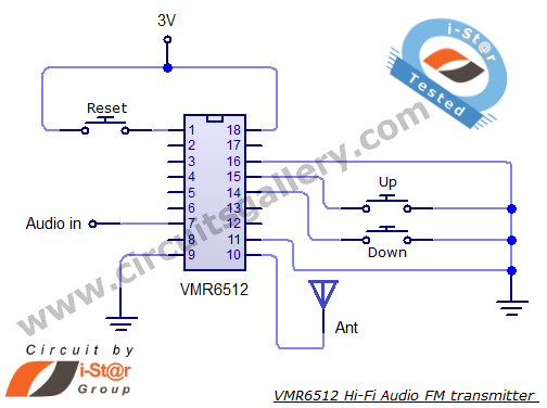
This article provides the circuit schematics for an FM transmitter along with the necessary explanations. The primary component utilized is the VMR6512 IC, a highly integrated FM audio signal transmitter chip designed for Hi-Fi audio applications. This chip can...
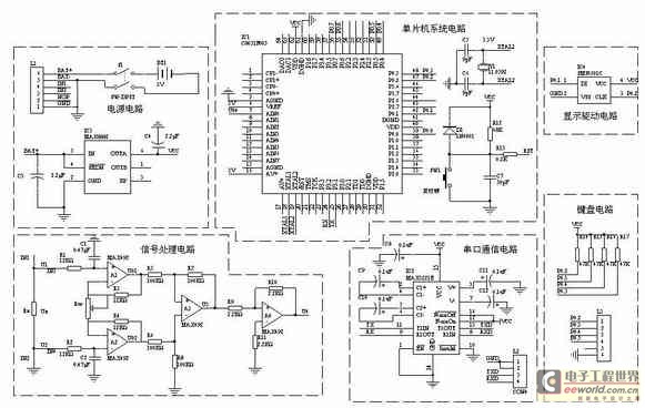
A one-chip computer has been utilized to design this survey meter, which directly displays the measured resistance on an LCD screen. The measurement range extends from 0 to 9999 kΩ, and the device can simultaneously store the measured data,...
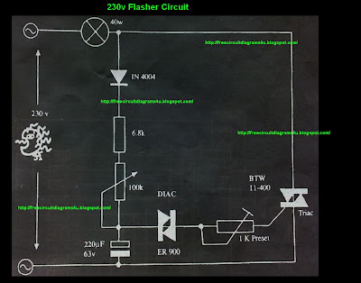
This circuit operates with 230V and can be used to decorate parties. It features a DIAC ER 900 and a TRIAC BTW 11-400. The circuit utilizes a DIAC (Diode for Alternating Current) and a TRIAC (Triode for Alternating Current) to...
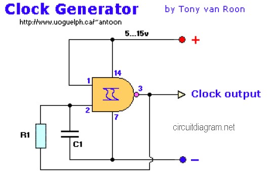
The following diagram is the clock generator circuit diagram built using NAND gate logic integrated circuits (ICs). The circuit can utilize either the IC 7400, which is a TTL type, or the IC 4011, which is a CMOS type....